Question
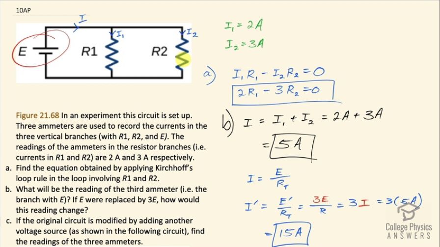
Figure 21.68 In an experiment this circuit is set up. Three ammeters are used to record the currents in the three vertical branches (with , , and ). The readings of the ammeters in the resistor branches (i.e. currents in and ) are 2 A and 3 A respectively.
- Find the equation obtained by applying Kirchhoff’s loop rule in the loop involving and .
- What will be the reading of the third ammeter (i.e. the branch with E)? If E were replaced by 3E, how would this reading change?
- If the original circuit is modified by adding another voltage source (as shown in the following circuit in Figure 21.69), find the readings of the three ammeters.
Final Answer
- ,
- , ,
Solution video
OpenStax College Physics for AP® Courses, Chapter 21, Problem 10 (Test Prep for AP® Courses)
vote with a rating of
votes with an average rating of
.
Video Transcript
This is College Physics Answers with Shaun Dychko. We have a circuit with a battery and a resistor R 1 and another resistor R 2, there's this total current I coming out of the battery and then that current splits at this junction into I 1 going through resistor one and then I 2 going through resistor two. The question in part (a) is find an equation that you get with Kirchhoff's Loop rule in the loop involving R 1 and R 2. So first let's label what that loop is; this is the loop here with both R 1 and R 2. Let's choose a starting point for traversing this loop. Suppose we start here when we go upwards through R 1, we'll be traversing this resistor in the opposite direction to what we imagine is the direction of the current and when doing that this is a positive change in potential because we're starting at the low potential position here and ending at the high potential position here where the current began. So going in this direction is a positive change in potential equal to I 1 multiplied by R 1 and so that's this term here. And then we continue traversing the loop in this clockwise direction and as we go down through R 2— this is in the same direction as the current— so our traversal direction and the current direction are the same so when doing that across a resistor that is a drop in potential and so we have a minus sign here to reflect that minus I 2 times R 2. And then we return back to our starting position and once we are at our starting position, we say equals zero and that's always how it is with Kirchhoff's Loop rule and it's essentially a statement that energy is conserved so for every increase in potential, there's an equal amount of decrease in potential in any closed loop. Substituting in the currents given to us in the question we know that I 1 is 2 amps and I 2 is 3 amps and we can replace I 1 with 2 and I 2 with 3 so we'll get 2R 1 minus 3R 2 equals zero. Alright! Part (b) says what will the reading of the third ammeter in this branch here in other words what is I with no subscript? And we can calculate that by by using the junction rule, which is to say that the current that goes into a junction like this one say, which is I, equals the total current coming out of that junction, which is I 1 plus I 2 and I 1 is 2 amps, I 2 is 3 amps and that total is 5 amps. And if E were replaced by an emf that was 3 times what it was originally, the reading will change because the original current is E divided by total resistance we don't know what the resistance is but it doesn't matter we can just write R T here and the current after replacing the battery with one that has three times the emf, we'll call this I prime, equals this new emf—E prime— divided by the same resistance—R total— and E prime we are told is 3 times E and E over R is this is R T still... E over R T is I and so we are going 3 times I, which is going to be 15 amps. Alright! If the original circuit is modified by adding another voltage source here and it has an emf of 2 times E what are the readings on the three ammeters? So we'll call this I prime and it's a different I prime than this one (sorry about that... bit of confusion maybe) this is a new I prime here I 1 prime and I 2 prime these primes label when we have this new emf here. We are going to use Kirchhoff's Loop rule here first we need to label the loop that includes both the batteries and R 2 and we are going to traverse this loop in a clockwise direction and beginning here say and so when we begin here, we are going to traverse this 2E battery starting at its negative terminal and ending at its positive terminal in which case this is going to be an increase in potential and so we have 2E to represent that in our Kirchhoff Loop rule. Then we are traversing this resistor R 2 in the same direction as our current and so that's going to be a drop in potential so that's minus I 2 prime times R 2 then continuing along here we traverse this battery from negative to positive and that's an increase in potential so we have plus E there that equals zero and then you can add I 2 primeR 2 to both sides and then switch the sides around and collect 2E plus E is 3E and then divide both sides by R 2 to solve for I 2 prime, it's going to be 3E divided by R 2. Now we don't know what R 2 is but we do have information about the circuit before the 2E battery was introduced and so the current I 2 that we had a while ago in part (a) was E divided by R 2 because the potential across this resistor is E since it's connected in parallel with this resistor directly across this potential E and we know that E divided by R 2 is some known number—3 amps— and we can replace E over R 2 then with the original I 2 so I 2 prime then is 3 times I 2 and that's 3 times 3 amps, which is 9 amps. Okay! And then let's make a new Kirchhoff Loop rule that involves R 1 and we can do that with this loop here containing only the battery with the emf E and the resistor R 1. So if we begin here suppose we traverse this resistor R 1 in the same direction as the current and that's going to be a drop in potential so we have a negative I 1 prime times R 1 and then we continue along here going up from the negative terminal to the positive terminal of this battery and that's an increase in potential of plus E all that equals zero add I 1 primeR 1 to both sides and then divide both sides by R 1 and then switch the sides around and you get I 1 prime equals E over R 1 which is the same as the original I 1 current that we had before this battery was introduced so this battery changes nothing about the current that goes through R 1 so it will be still 2 amps. The total current going through the circuit here—I prime— is I 1 prime plus I 2 prime, which is 2 plus 9 which is 11 amps.