Question
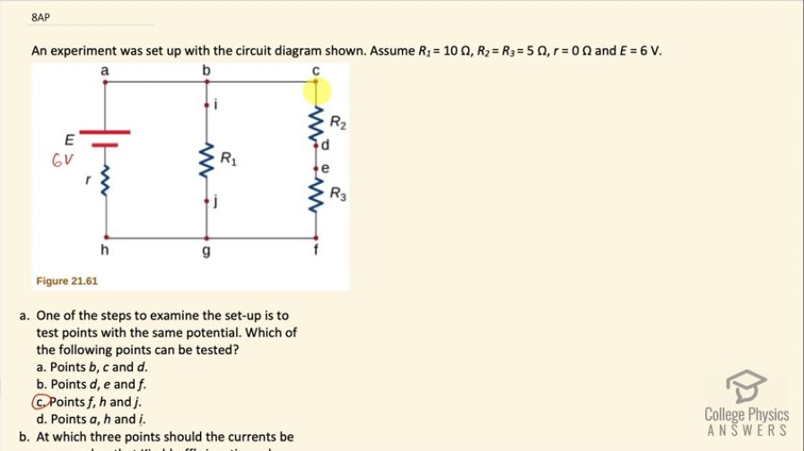
An experiment was set up with the circuit diagram shown in Figure 21.61. Assume , , , and .
- One of the steps to examine the set-up is to test points with the same potential. Which of the following points can be tested?
- Points b, c and d.
- Points d, e and f.
- Points f, h and j.
- Points a, h and i.
- At which three points should the currents be measured so that Kirchhoff’s junction rule can be directly confirmed?
- Points b, c and d.
- Points d, e and f.
- Points f, h and j.
- Points a, h and i.
- If the current in the branch with the voltage source is upward and currents in the other two branches are downward, i.e. Ia = Ii + Ic, identify which of the following can be true? Select two answers.
- li = Ij - If
- Ie = Ih - Ii
- Ic = Ij - Ia
- Id = Ih - Ij
- The measurements reveal that the current through R1 is 0.5 A and R3 is 0.6 A. Based on your knowledge of Kirchoff’s laws, confirm which of the following statements are true.
- The measured current for R1 is correct but for R3 is incorrect.
- The measured current for R3 is correct but for R1 is incorrect.
- Both the measured currents are correct.
- Both the measured currents are incorrect.
- The graph shown in the following Figure 21.62 is the energy dissipated at R1 as a function of time. Which of the following among Figures 21.63 and Figure 21.65 shows the graph for energy dissipated at R2 as a function of time?
Final Answer
- (c)
- (c)
- (b) and (d)
- (b)
- (c)
Solution video
OpenStax College Physics for AP® Courses, Chapter 21, Problem 8 (Test Prep for AP® Courses)
vote with a rating of
votes with an average rating of
.
Video Transcript
This is College Physics Answers with Shaun Dychko. We have a circuit with an emf here of 6 volts connected to two branches that are in parallel; this branch has a resistor R 1 with a resistance of 10 ohms and this other branch has resistor R 2 and R 3 being equal to 5 ohms each... this internal resistance is zero so it might as well not be written here, we can just replace it with a wire. Okay! So part (a) asks one of the steps to examine this circuit is to test points with the same potential so which of the following points will have the same potential? Points f, h and j will because points f, h and j are just connected by wires, which we assume on a schematic diagram like this have zero resistance and so they are all the same potential because there's no resistance between these points. You can look at all these other options and you will find that there are resistors between some of the points in these other options that are not correct. So consider option (a) b, c and d... we have b here, c here they are at the same potential but then d on the other hand is on the other side of this resistor and so it will have a different potential because there will be a potential drop across this resistor so b, c and d are not all at the same potential and the same sort of thing can be said for (b) and (d) options here. Alright! Question (b): at which three points should the currents be measured so that Kirchhoff's junction rule can be directly confirmed? So to confirm the junction rule, we need to be able to measure the currents on all parts coming out of a single point and so we have these positions at f, h and j are going to be used to confirm the junction rule because these are measuring currents that are all going through junction g. So the current is going to come into g through j so the current I j is going to go into this point g and then from here... well, we will also going to have current going into g from point f and then these two together will go to h and so we'll have a current h here. So when we compare, you know, I j plus I f this total should equal I h in order to confirm the junction rule— the total current going into a junction equals the total current coming out in other words. Okay! Just to exclude option (a) suppose it's going to consider points b, c and d... b, c and d here... c and d are on a single branch they are not... I mean the current through c and d are definitely going to be the same because they are on the same branch and they will not equal the current going into junction b because the current will split at this point through R 1 and then through this branch through R 2 and R 3 so this will not be usable to confirm the junction rule what you would find is that currents c and d are equal and they will be less than the current at position b but that's not a way to confirm the junction rule. Okay! If the current in the branch with a voltage source is upwards and currents on the other two branches are downward identify which of the following can be true and we have to select two answers. So the current here is upward and the current in these two branches is downward. Option (b) is going to be correct so I e is going to be I h minus I i so current at e is going to be current at h minus current at i because current at h is going to be the total of i and e (let's erase some of this other stuff that's in the way now) we are going to have current i here— it's also current j but they are on the same branch so they are equal. So current i goes into junction g, current e goes into junction g as well and current i plus current e is going to have to equal the current coming out at junction g which will be the current I h and then they chose to write that a little differently so I e is on one hand and so I e is I h minus I i and that's what they have written here. Okay and then option (d) is also correct so current at d equals current at h minus current at j. So let's erase some of the extraneous stuff here... what we are looking at now again is d equals h minus j. Okay! So we have current at d equals current at h minus current at j which is kind of the same story as before. So we have this total I h take away from that the current through j and you would be left with the current through d and that's option (d) here. Then measurements reveal the current through R 1 is 0.5 amps and R 3 is 0.6 amps so here's R 3 and we are told that the current through R 3 is 0.6 amps and the current through R 1 is 0.5 amps allegedly although we're going to see that something's wrong with this conclusion. So which of the following statements are true? Well we can calculate the current because we are given enough information we know that the voltage across R 1 is 6 volts because its internal resistance is zero and so this R 1 is across the battery so there's a voltage of 6 volts across here and the resistance is 10 ohms and so we can calculate the current through R 1 then it is 6 volts divided by 10 ohms, which is 0.6 amps. Now this also is going to be the current through this branch since the total resistance of these two resistances in series is also 10 ohms and so their current will be the same and the current is going to be the same in both these resistors since they are in series and that's going to be 0.6 amps as well. So I 1 should be 0.6 and I 3 is 0.6 and so the current through R 3 is correct but the 0.5 allegedly measured for R 1 is incorrect so the answer is (b). This graph shows the energy dissipated in R 1 is a function of time and the question is which of the following graphs show energy dissipated in R 2 as a function of time. Well, the current through R 1 is the same as the current through R 2 because each of these branches in parallel have the same resistance and so there will be the same current through them since they have the same voltage across them and the energy is the power dissipated multiplied by time and power can be replaced with I squared times resistance times time. So the energy at time t 1 through resistor one is going to be the current squared and there's no subscript on the current since as we mention the current through the resistor one is the same as the current through resistor two so we'll just call it I it's going to be I squared times resistance one times t 1. Now the energy through resistor two at time t 1 is going to be I squared times resistance two but resistance two is half of resistance one since you know 5 ohms is half of 10 ohms and this I squaredR 1t is E 1 so we replace that with E 1 and we can see that E 1's getting divided by 2 to find E 2. So we need to find a graph that has E 1 over 2, which is option (c).