
Chapter 21: Circuits and DC Instruments
90 problems solved · Free preview of every solution shows how it’s started · Watch the full videos with a free 7-day trial →
Image: Airman 1st Class Mike Meares, United States Air Force


Section
21.1 Resistors in Series and Parallel
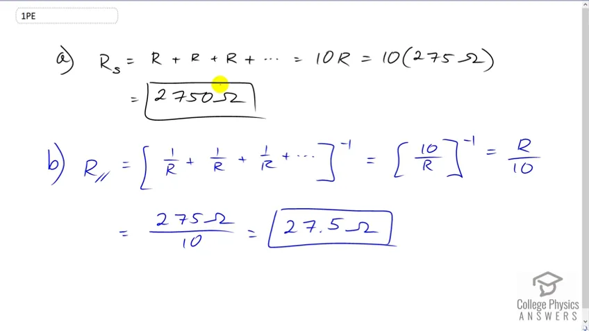 0:47Problem 1Free(a) What is the resistance of ten resistors connected in series? (b) In parallel?
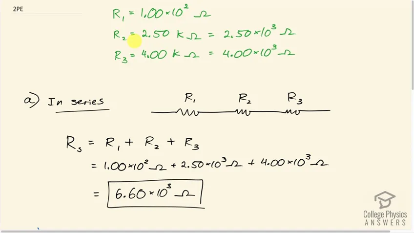 3:23PreviewProblem 2Full video with free trial(a) What is the resistance of a , a , and a resistor connected in series? (b) In parallel?
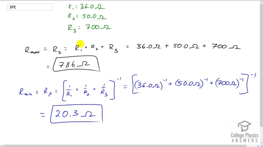 0:56PreviewProblem 3Full video with free trialWhat are the largest and smallest resistances you can obtain by connecting a , a , and a resistor together?
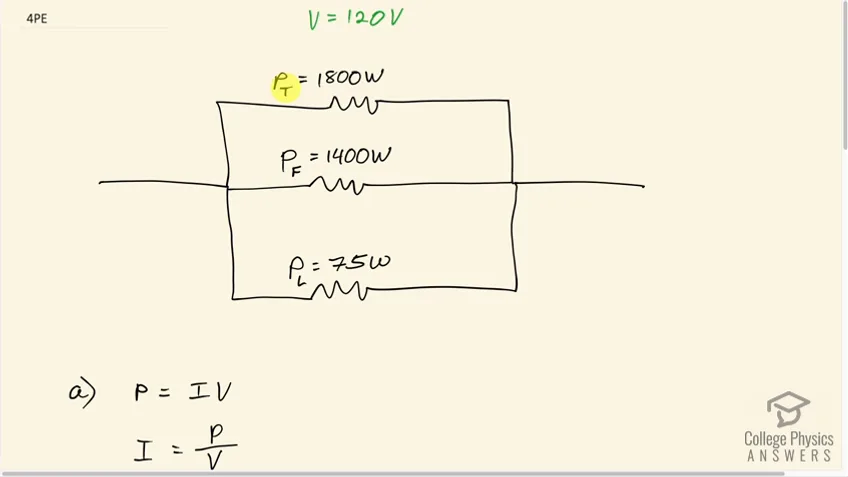 1:54PreviewProblem 4Full video with free trialAn 1800-W toaster, a 1400-W electric frying pan, and a 75-W lamp are plugged into the same outlet in a 15-A, 120-V circuit. (The three devices are in parallel when plugged into the same socket.). (a) What current is drawn by each device? (b) Will this combination blow the 15-A fuse?
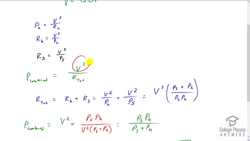 3:12PreviewProblem 5Full video with free trialYour car’s 30.0-W headlight and 2.40-kW starter are ordinarily connected in parallel in a 12.0-V system. What power would one headlight and the starter consume if connected in series to a 12.0-V battery? (Neglect any other resistance in the circuit and any change in resistance in the two devices.)
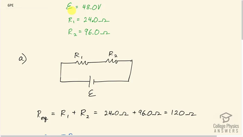 3:24PreviewProblem 6Full video with free trial(a) Given a 48.0-V battery and and resistors, find the current and power for each when connected in series. (b) Repeat when the resistances are in parallel.
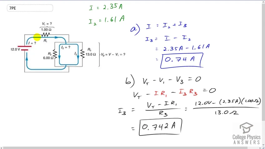 2:45PreviewProblem 7Full video with free trialReferring to the example combining series and parallel circuits and Figure 21.6, calculate in the following two different ways: (a) from the known values of and ; (b) using Ohm’s law for . In both parts explicitly show how you follow the steps in the Problem-Solving Strategies for Series and Parallel Resistors. From the example: , and .
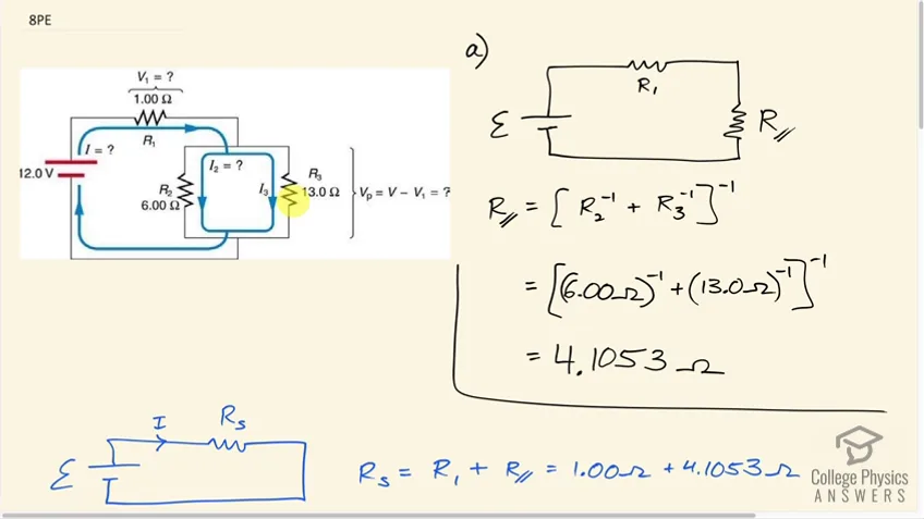 7:08PreviewProblem 8Full video with free trialReferring to Figure 21.6: (a) Calculate (b) Find the total power supplied by the source and compare it with the sum of the powers dissipated by the resistors.
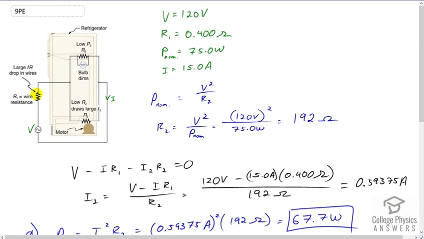 5:58PreviewProblem 9Full video with free trialRefer to Figure 21.7 and the discussion of lights dimming when a heavy appliance comes on. (a) Given the voltage source is 120 V, the wire resistance is , and the bulb is nominally 75.0 W, what power will the bulb dissipate if a total of 15.0 A passes through the wires when the motor comes on? Assume negligible change in bulb resistance. (b) What power is consumed by the motor?
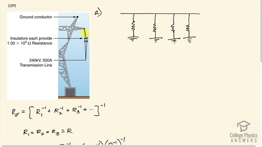 5:00PreviewProblem 10Full video with free trialA 240-kV power transmission line carrying is hung from grounded metal towers by ceramic insulators, each having a resistance. Figure 21.51. (a) What is the resistance to ground of 100 of these insulators? (b) Calculate the power dissipated by 100 of them. (c) What fraction of the power carried by the line is this? Explicitly show how you follow the steps in the Problem-Solving Strategies for Series and Parallel Resistors.
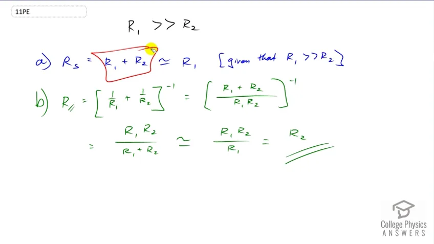 1:17PreviewProblem 11Full video with free trialShow that if two resistors and are combined and one is much greater than the other ( ): (a) Their series resistance is very nearly equal to the greater resistance . (b) Their parallel resistance is very nearly equal to smaller resistance .
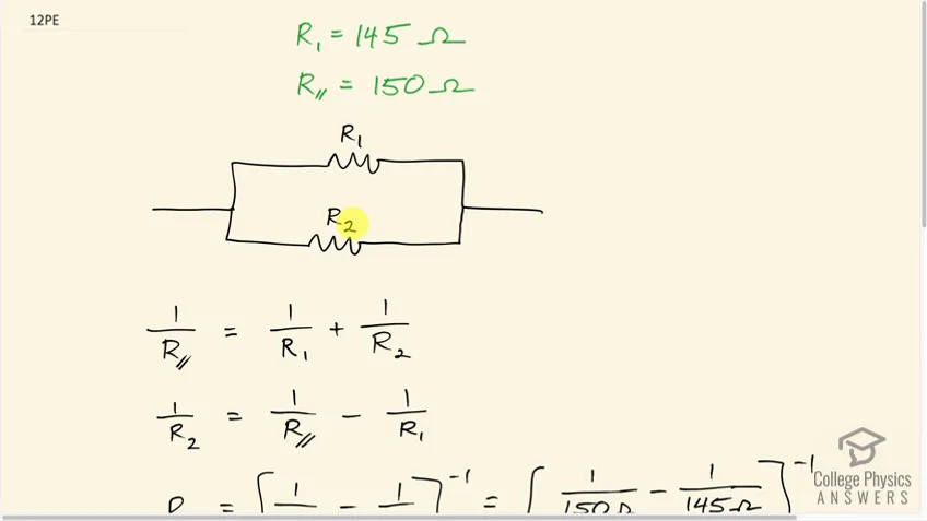 1:54PreviewProblem 12Full video with free trialTwo resistors, one having a resistance of , are connected in parallel to produce a total resistance of . (a) What is the value of the second resistance? (b) What is unreasonable about this result? (c) Which assumptions are unreasonable or inconsistent?
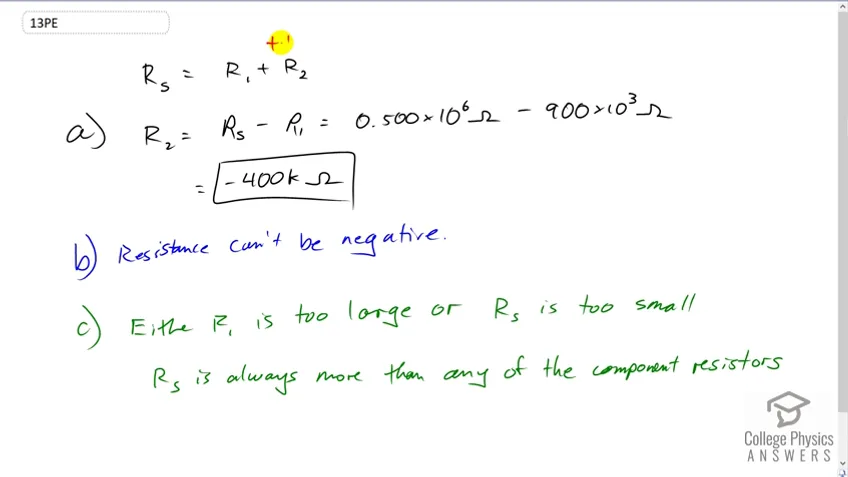 2:08PreviewProblem 13Full video with free trialTwo resistors, one having a resistance of , are connected in series to produce a total resistance of . (a) What is the value of the second resistance? (b) What is unreasonable about this result? (c) Which assumptions are unreasonable or inconsistent?
21.2 Electromotive Force: Terminal Voltage
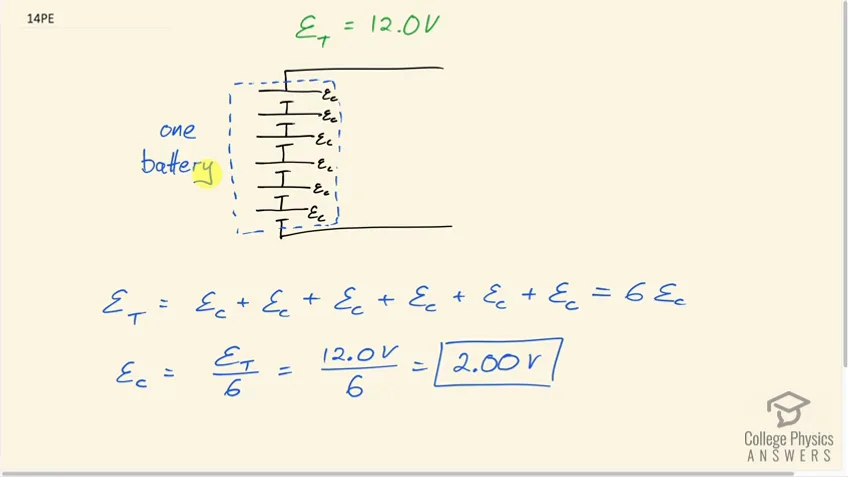 1:50PreviewProblem 14Full video with free trialStandard automobile batteries have six lead-acid cells in series, creating a total emf of 12.0 V. What is the emf of an individual lead-acid cell?
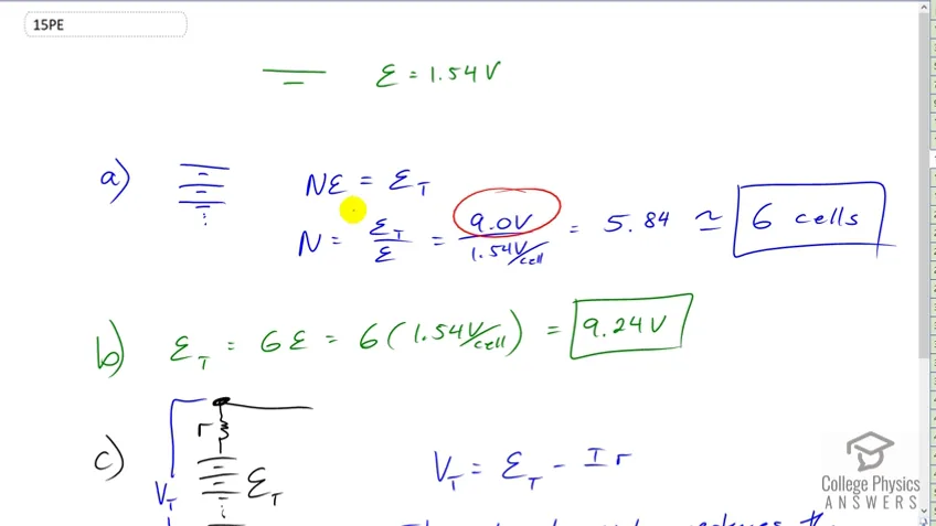 2:00PreviewProblem 15Full video with free trialCarbon-zinc dry cells (sometimes referred to as non- alkaline cells) have an emf of 1.54 V, and they are produced as single cells or in various combinations to form other voltages. (a) How many 1.54-V cells are needed to make the common 9-V battery used in many small electronic devices? (b) What is the actual emf of the approximately 9-V battery? (c) Discuss how internal resistance in the series connection of cells will affect the terminal voltage of this approximately 9-V battery.
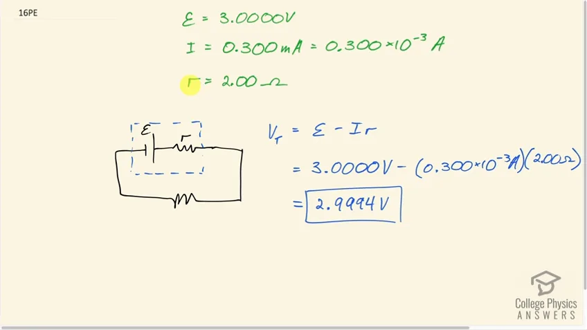 0:46PreviewProblem 16Full video with free trialWhat is the output voltage of a 3.0000-V lithium cell in a digital wristwatch that draws 0.300 mA, if the cell’s internal resistance is ?
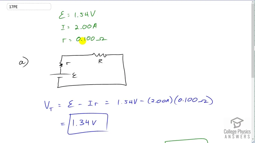 1:43PreviewProblem 17Full video with free trial(a) What is the terminal voltage of a large 1.54-V carbon- zinc dry cell used in a physics lab to supply 2.00 A to a circuit, if the cell’s internal resistance is ? (b) How much electrical power does the cell produce? (c) What power goes to its load?
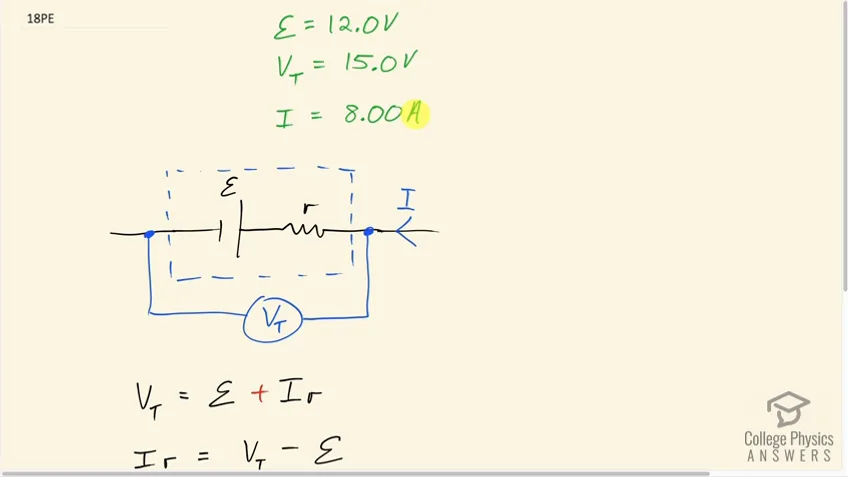 2:31PreviewProblem 18Full video with free trialWhat is the internal resistance of an automobile battery that has an emf of 12.0 V and a terminal voltage of 15.0 V while a current of 8.00 A is charging it?
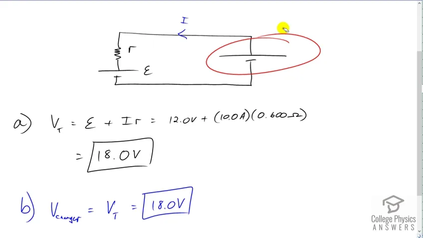 2:30PreviewProblem 19Full video with free trial(a) Find the terminal voltage of a 12.0-V motorcycle battery having a internal resistance, if it is being charged by a current of 10.0 A. (b) What is the output voltage of the battery charger?
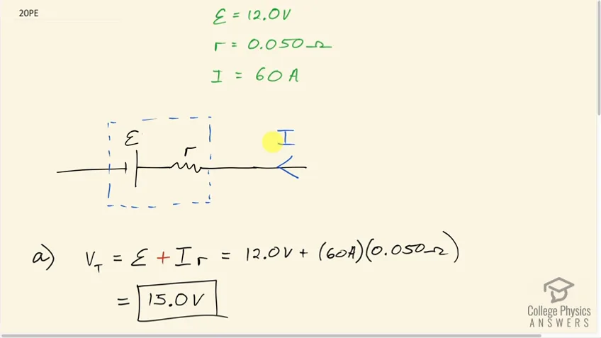 5:16PreviewProblem 20Full video with free trialA car battery with a 12-V emf and an internal resistance of is being charged with a current of 60 A. Note that in this process the battery is being charged. (a) What is the potential difference across its terminals? (b) At what rate is thermal energy being dissipated in the battery? (c) At what rate is electric energy being converted to chemical energy? (d) What are the answers to (a) and (b) when the battery is used to supply 60 A to the starter motor?
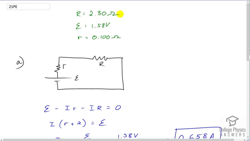 2:31PreviewProblem 21Full video with free trialThe hot resistance of a flashlight bulb is , and it is run by a 1.58-V alkaline cell having a internal resistance. (a) What current flows? (b) Calculate the power supplied to the bulb using . (c) Is this power the same as calculated using ?
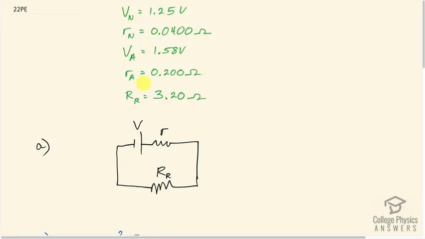 4:28PreviewProblem 22Full video with free trialThe label on a portable radio recommends the use of rechargeable nickel-cadmium cells (nicads), although they have a 1.25-V emf while alkaline cells have a 1.58-V emf. The radio has a resistance. (a) Draw a circuit diagram of the radio and its batteries. Now, calculate the power delivered to the radio. (b) When using Nicad cells each having an internal resistance of . (c) When using alkaline cells each having an internal resistance of . (d) Does this difference seem significant, considering that the radio’s effective resistance is lowered when its volume is turned up?
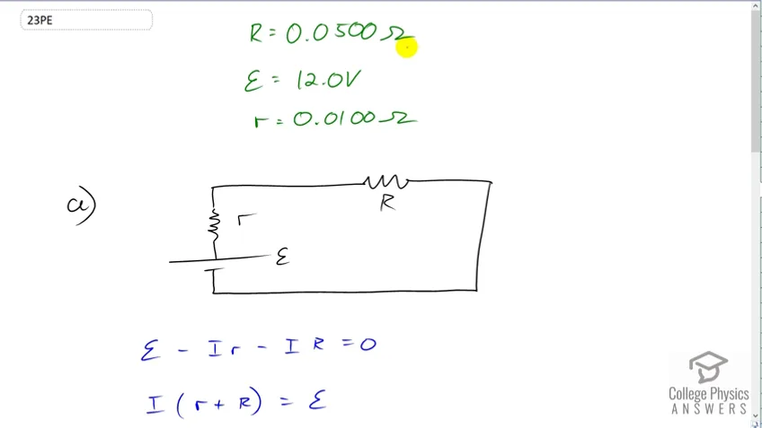 2:49PreviewProblem 23Full video with free trialAn automobile starter motor has an equivalent resistance of and is supplied by a 12.0-V battery with a internal resistance. (a) What is the current to the motor? (b) What voltage is applied to it? (c) What power is supplied to the motor? (d) Repeat these calculations for when the battery connections are corroded and add to the circuit. (Significant problems are caused by even small amounts of unwanted resistance in low-voltage, high-current applications.)
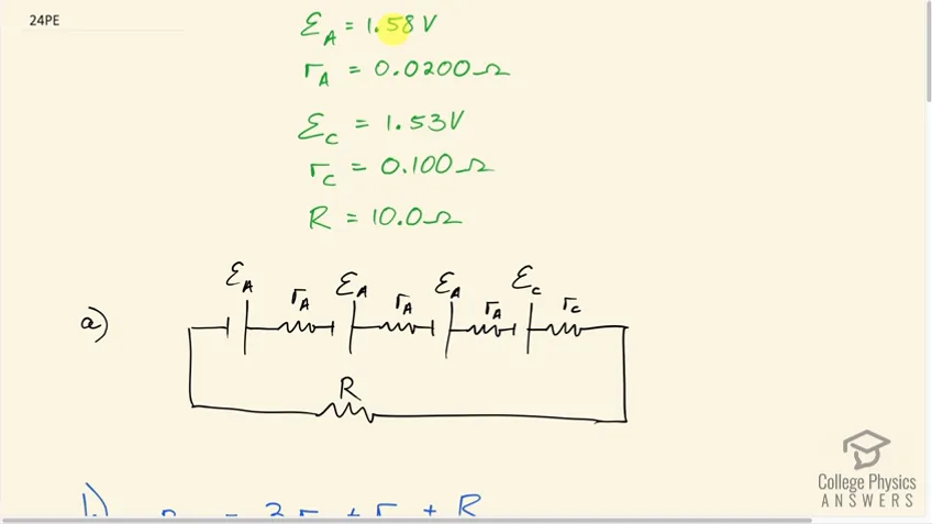 6:04PreviewProblem 24Full video with free trialA child’s electronic toy is supplied by three 1.58-V alkaline cells having internal resistances of in series with a 1.53-V carbon-zinc dry cell having a internal resistance. The load resistance is . (a) Draw a circuit diagram of the toy and its batteries. (b) What current flows? (c) How much power is supplied to the load? (d) What is the internal resistance of the dry cell if it goes bad, resulting in only 0.500 W being supplied to the load?
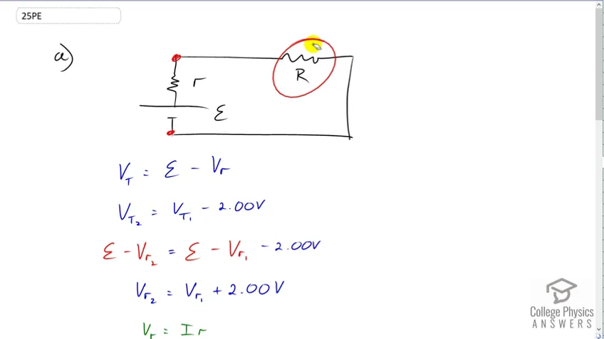 3:52PreviewProblem 25Full video with free trial(a) What is the internal resistance of a voltage source if its terminal voltage drops by 2.00 V when the current supplied increases by 5.00 A? (b) Can the emf of the voltage source be found with the information supplied?
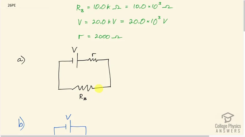 4:47PreviewProblem 26Full video with free trialA person with body resistance between his hands of accidentally grasps the terminals of a 20.0-kV power supply. (Do NOT do this!) (a) Draw a circuit diagram to represent the situation. (b) If the internal resistance of the power supply is , what is the current through his body? (c) What is the power dissipated in his body? (d) If the power supply is to be made safe by increasing its internal resistance, what should the internal resistance be for the maximum current in this situation to be 1.00 mA or less? (e) Will this modification compromise the effectiveness of the power supply for driving low-resistance devices? Explain your reasoning.
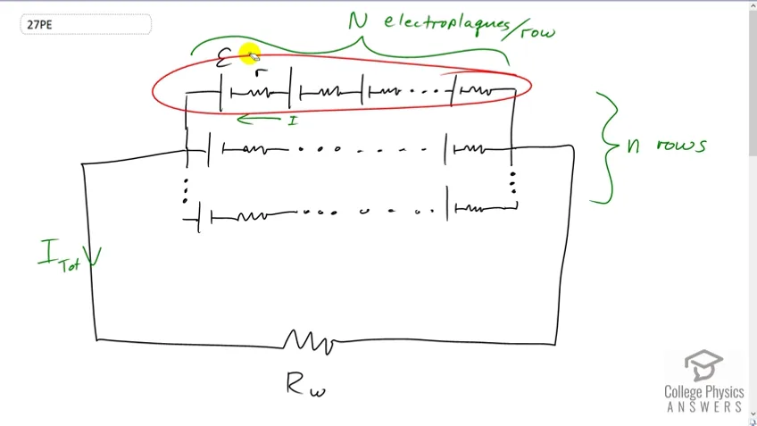 4:20PreviewProblem 27Full video with free trialElectric fish generate current with biological cells called electroplaques, which are physiological emf devices. The electroplaques in the South American eel are arranged in 140 rows, each row stretching horizontally along the body and each containing 5000 electroplaques. Each electroplaque has an emf of 0.15 V and internal resistance of . If the water surrounding the fish has resistance of , how much current can the eel produce in water from near its head to near its tail?
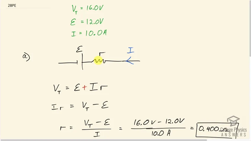 4:20PreviewProblem 28Full video with free trialA 12.0-V emf automobile battery has a terminal voltage of 16.0 V when being charged by a current of 10.0 A. (a) What is the battery’s internal resistance? (b) What power is dissipated inside the battery? (c) At what rate (in ) will its temperature increase if its mass is 20.0 kg and it has a specific heat of , assuming no heat escapes?
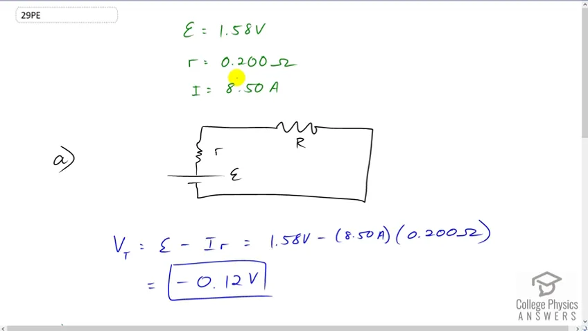 2:02PreviewProblem 29Full video with free trialA 1.58-V alkaline cell with a internal resistance is supplying 8.50 A to a load. (a) What is its terminal voltage? (b) What is the value of the load resistance? (c) What is unreasonable about these results? (d) Which assumptions are unreasonable or inconsistent?
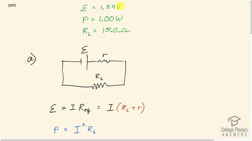 4:25PreviewProblem 30Full video with free trial(a) What is the internal resistance of a 1.54-V dry cell that supplies 1.00 W of power to a bulb? (b) What is unreasonable about this result? (c) Which assumptions are unreasonable or inconsistent?
21.3 Kirchhoff's Rules
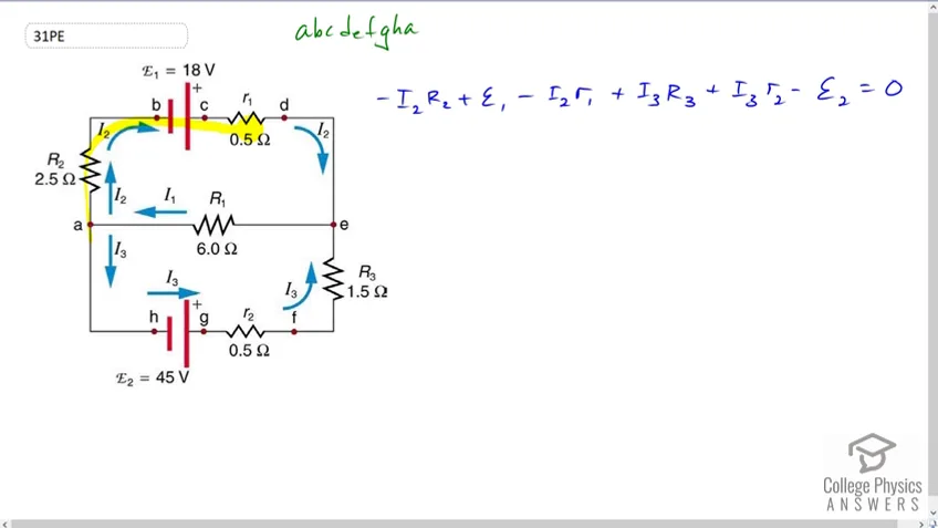 1:33PreviewProblem 31Full video with free trialApply the loop rule to loop abcdefgha in Figure 21.25.
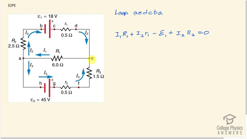 1:36PreviewProblem 32Full video with free trialApply the loop rule to loop aedcba in Figure 21.25.
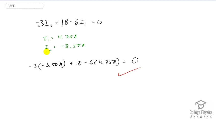 0:30PreviewProblem 33Full video with free trialVerify the second equation in Example 21.5 by substituting the values found for the currents and .
The equation is . , .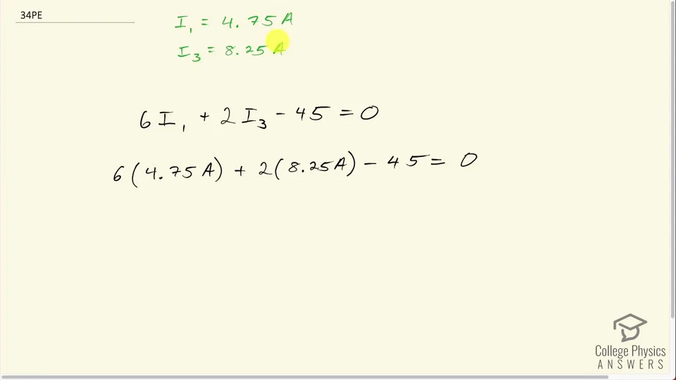 0:53PreviewProblem 34Full video with free trial
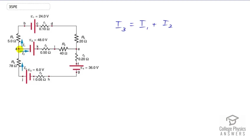 0:31PreviewProblem 35Full video with free trialApply the junction rule at point a in Figure 21.52.
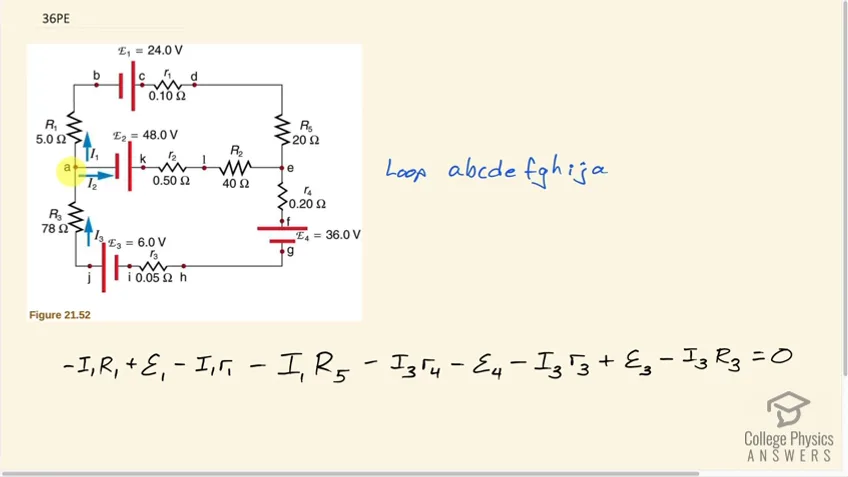 2:53PreviewProblem 36Full video with free trialApply the loop rule to loop abcdefghija in Figure 21.52.
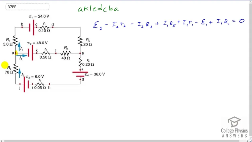 2:18PreviewProblem 37Full video with free trialApply the loop rule to loop akledcba in Figure 21.52.
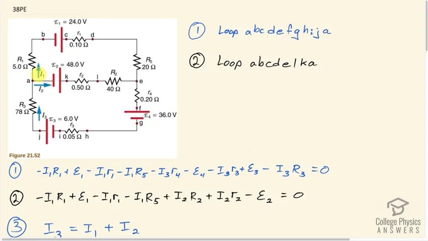 14:14PreviewProblem 38Full video with free trialFind the currents flowing in the circuit in Figure 21.52. Explicitly show how you follow the steps in the Problem- Solving Strategies for Series and Parallel Resistors.
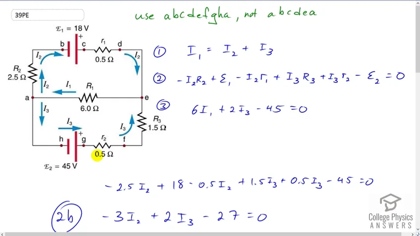 7:49PreviewProblem 39Full video with free trialSolve Example 21.5, but use loop abcdefgha instead of loop abcdea. Explicitly show how you follow the steps in the Problem-Solving Strategies for Series and Parallel Resistors.
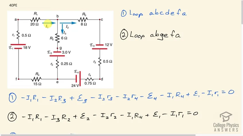 15:30PreviewProblem 40Full video with free trialFind the currents flowing in the circuit in Figure 21.47.
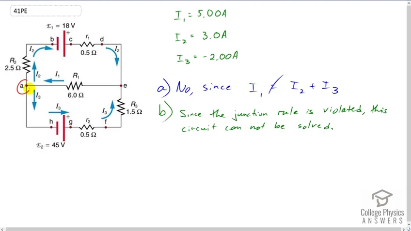 0:30PreviewProblem 41Full video with free trialConsider the circuit in Figure 21.53, and suppose that the emfs are unknown and the currents are given to be , , and . (a) Could you find the emfs? (b) What is wrong with the assumptions?
21.4 DC Voltmeters and Ammeters
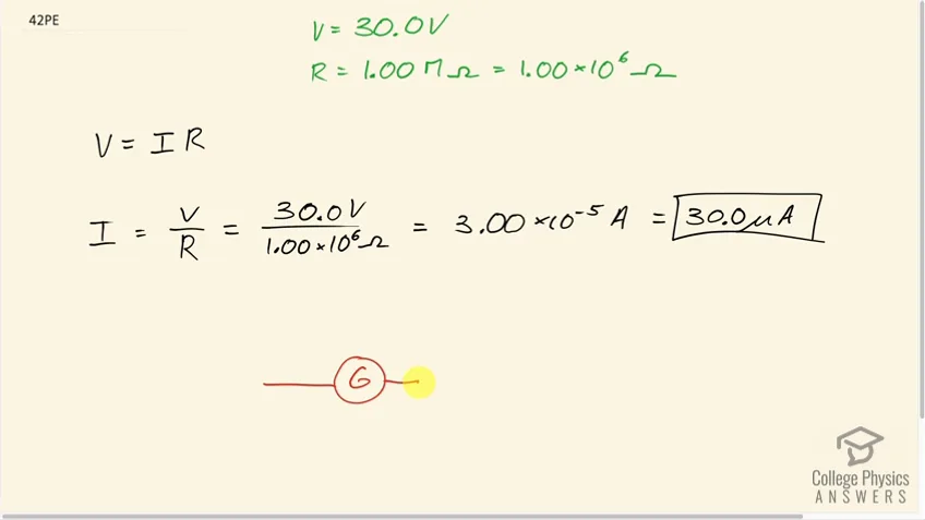 1:42PreviewProblem 42Full video with free trialWhat is the sensitivity of the galvanometer (that is, what current gives a full-scale deflection) inside a voltmeter that has a 1.00-M Ω resistance on its 30.0-V scale?
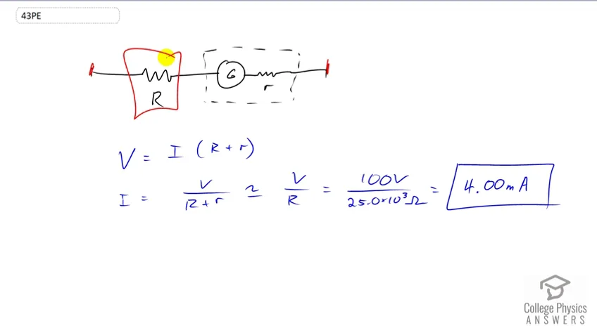 1:08PreviewProblem 43Full video with free trialWhat is the sensitivity of the galvanometer (that is, what current gives a full-scale deflection) inside a voltmeter that has a resistance on its 100-V scale?
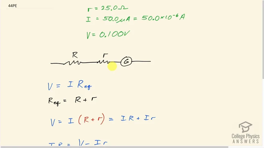 2:14PreviewProblem 44Full video with free trialFind the resistance that must be placed in series with a galvanometer having a sensitivity (the same as the one discussed in the text) to allow it to be used as a voltmeter with a 0.100-V full-scale reading.
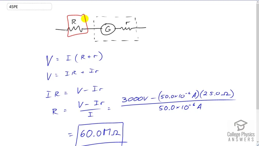 1:46PreviewProblem 45Full video with free trialFind the resistance that must be placed in series with a galvanometer having a sensitivity (the same as the one discussed in the text) to allow it to be used as a voltmeter with a 3000-V full-scale reading. Include a circuit diagram with your solution.
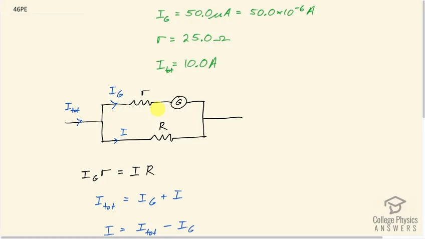 2:56PreviewProblem 46Full video with free trialFind the resistance that must be placed in parallel with a galvanometer having a sensitivity (the same as the one discussed in the text) to allow it to be used as an ammeter with a 10.0-A full-scale reading. Include a circuit diagram with your solution.
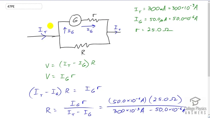 1:55PreviewProblem 47Full video with free trialFind the resistance that must be placed in parallel with a galvanometer having a sensitivity (the same as the one discussed in the text) to allow it to be used as an ammeter with a 300-mA full-scale reading.
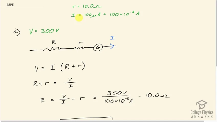 1:52PreviewProblem 48Full video with free trialFind the resistance that must be placed in series with a galvanometer having a sensitivity to allow it to be used as a voltmeter with: (a) a 300-V full-scale reading, and (b) a 0.300-V full-scale reading.
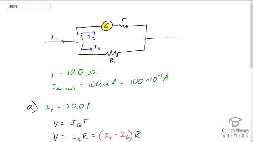 2:50PreviewProblem 49Full video with free trialFind the resistance that must be placed in parallel with a galvanometer having a sensitivity to allow it to be used as an ammeter with: (a) a 20.0-A full-scale reading, and (b) a 100-mA full-scale reading.
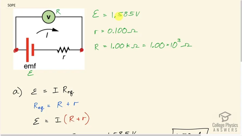 2:17PreviewProblem 50Full video with free trialSuppose you measure the terminal voltage of a 1.585-V alkaline cell having an internal resistance of by placing a voltmeter across its terminals. (See Figure 21.54.) (a) What current flows? (b) Find the terminal voltage. (c) To see how close the measured terminal voltage is to the emf, calculate their ratio.
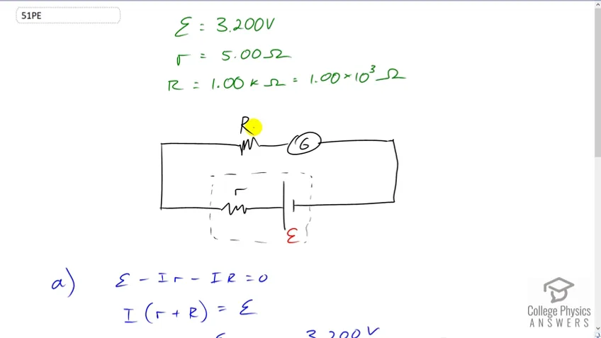 2:35PreviewProblem 51Full video with free trialSuppose you measure the terminal voltage of a 3.200-V lithium cell having an internal resistance of by placing a voltmeter across its terminals. (a) What current flows? (b) Find the terminal voltage. (c) To see how close the measured terminal voltage is to the emf, calculate their ratio.
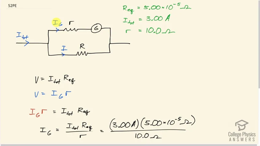 1:56PreviewProblem 52Full video with free trialA certain ammeter has a resistance of on its 3.00-A scale and contains a galvanometer. What is the sensitivity of the galvanometer?
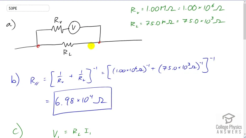 5:24PreviewProblem 53Full video with free trialA voltmeter is placed in parallel with a resistor in a circuit. (a) Draw a circuit diagram of the connection. (b) What is the resistance of the combination? (c) If the voltage across the combination is kept the same as it was across the resistor alone, what is the percent increase in current? (d) If the current through the combination is kept the same as it was through the resistor alone, what is the percentage decrease in voltage? (e) Are the changes found in parts (c) and (d) significant? Discuss.
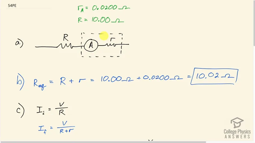 6:42PreviewProblem 54Full video with free trialA ammeter is placed in series with a resistor in a circuit. (a) Draw a circuit diagram of the connection. (b) Calculate the resistance of the combination. (c) If the voltage is kept the same across the combination as it was through the resistor alone, what is the percent decrease in current? (d) If the current is kept the same through the combination as it was through the resistor alone, what is the percent increase in voltage? (e) Are the changes found in parts (c) and (d) significant? Discuss.
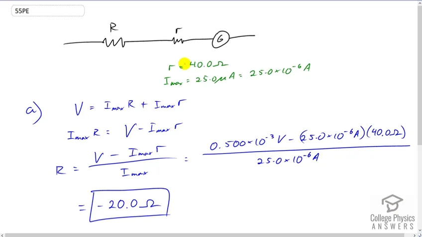 1:48PreviewProblem 55Full video with free trialSuppose you have a galvanometer with a sensitivity. (a) What resistance would you put in series with it to allow it to be used as a voltmeter that has a full-scale deflection for 0.500 mV? (b) What is unreasonable about this result? (c) Which assumptions are responsible?
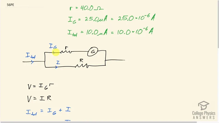 2:15PreviewProblem 56Full video with free trial(a) What resistance would you put in parallel with a galvanometer having a sensitivity to allow it to be used as an ammeter that has a full-scale deflection for ? (b) What is unreasonable about this result? (c) Which assumptions are responsible?
21.5 Null Measurements
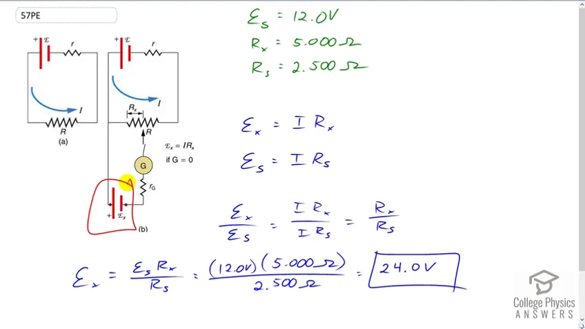 1:43PreviewProblem 57Full video with free trialWhat is the of a cell being measured in a potentiometer, if the standard cell’s emf is 12.0 V and the potentiometer balances for and ?
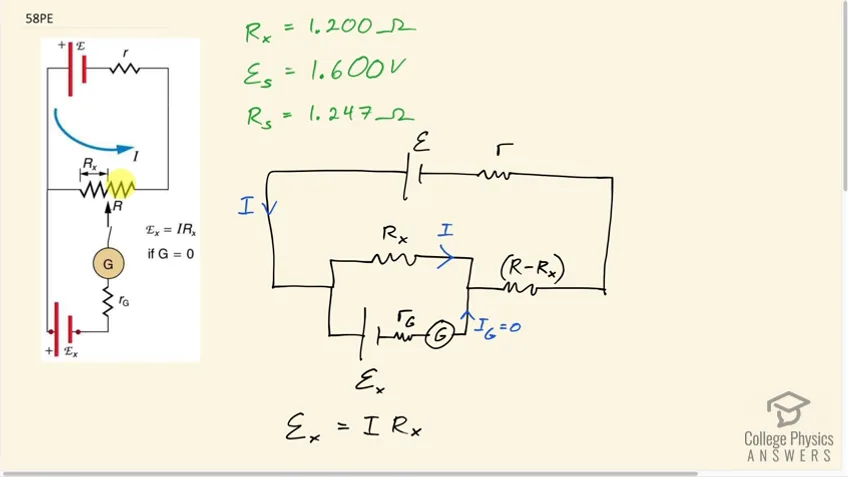 2:38PreviewProblem 58Full video with free trialCalculate the $\textrm{emf}\textrm{x}$ of a dry cell for which a potentiometer is balanced when $R\textrm{x} = 1.200\textrm{ }\OmegaR_\textrm{s} = 1.247\textrm{ }\Omega$ to balance the potentiometer.
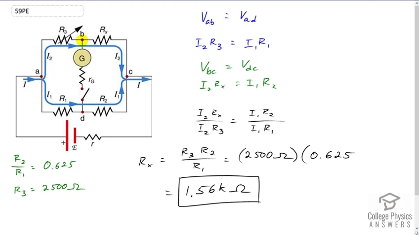 1:56PreviewProblem 59Full video with free trialWhen an unknown resistance is placed in a Wheatstone bridge, it is possible to balance the bridge by adjusting to be . What is if ?
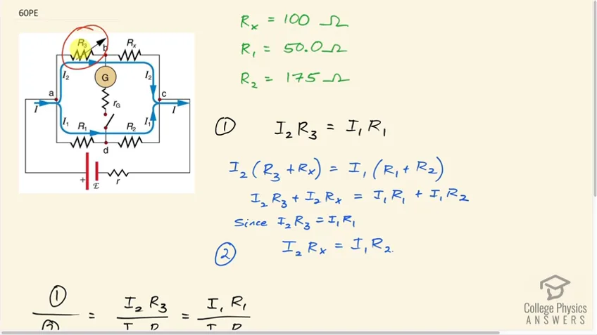 2:40PreviewProblem 60Full video with free trialTo what value must you adjust to balance a Wheatstone bridge, if the unknown resistance is , is , and is
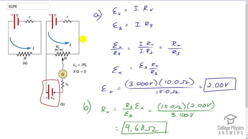 2:23PreviewProblem 61Full video with free trial(a) What is the unknown in a potentiometer that balances when is , and balances when is for a standard 3.000-V emf? (b) The same is placed in the same potentiometer, which now balances when is for a standard emf of 3.100 V. At what resistance will the potentiometer balance?
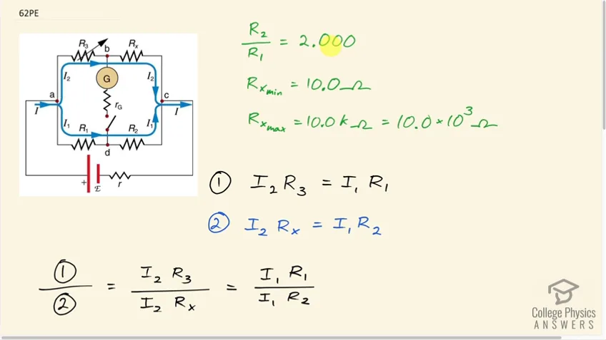 3:15PreviewProblem 62Full video with free trialSuppose you want to measure resistances in the range from $10.0\textrm{ } \Omega10.0\textrm{ k}\Omega\dfrac{R_2}{R_1} = 2.000R_3$ be adjustable?
21.6 DC Circuits Containing Resistors and Capacitors
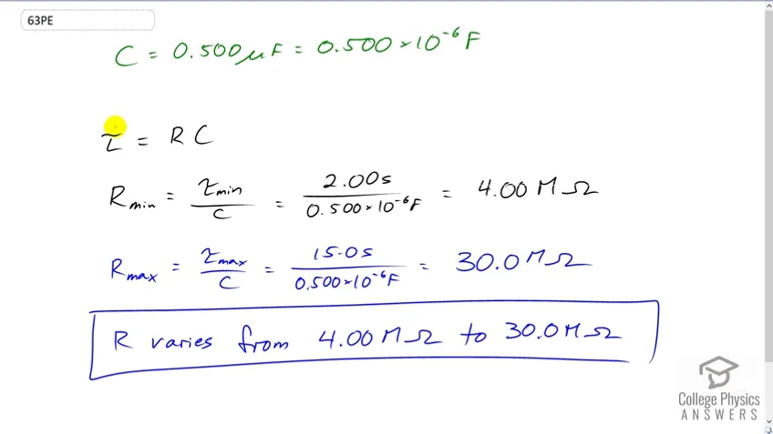 0:52PreviewProblem 63Full video with free trialThe timing device in an automobile’s intermittent wiper system is based on an time constant and utilizes a capacitor and a variable resistor. Over what range must be made to vary to achieve time constants from to ?
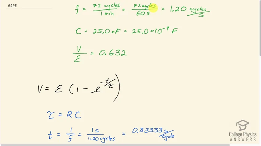 2:48PreviewProblem 64Full video with free trialA heart pacemaker fires 72 times a minute, each time a 25.0-nF capacitor is charged (by a battery in series with a resistor) to 0.632 of its full voltage. What is the value of the resistance?
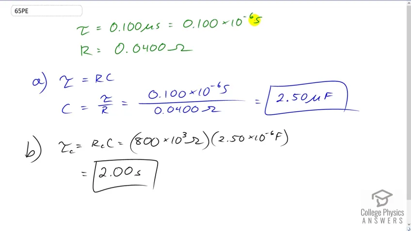 0:55PreviewProblem 65Full video with free trialThe duration of a photographic flash is related to an time constant, which is for a certain camera. (a) If the resistance of the flash lamp is during discharge, what is the size of the capacitor supplying its energy? (b) What is the time constant for charging the capacitor, if the charging resistance is ?
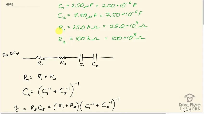 3:36PreviewProblem 66Full video with free trialA and a capacitor can be connected in series or parallel, as can a and a resistor. Calculate the four RC time constants possible from connecting the resulting capacitance and resistance in series.
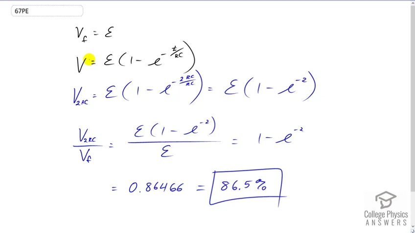 1:16PreviewProblem 67Full video with free trialAfter two time constants, what percentage of the final voltage, emf, is on an initially uncharged capacitor , charged through a resistance ?
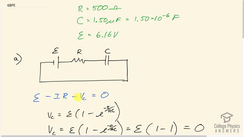 3:15PreviewProblem 68Full video with free trialA resistor, an uncharged capacitor, and a 6.16-V emf are connected in series. (a) What is the initial current? (b) What is the RC time constant? (c) What is the current after one time constant? (d) What is the voltage on the capacitor after one time constant?
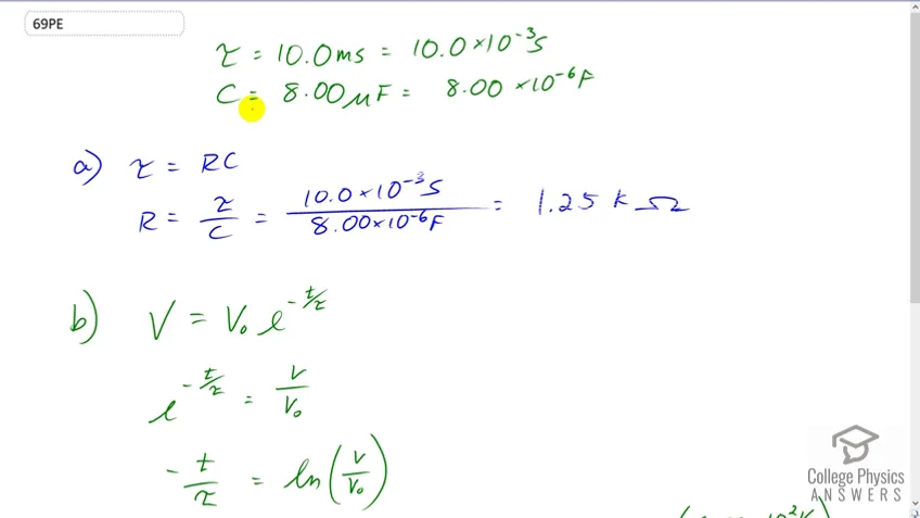 1:32PreviewProblem 69Full video with free trialA heart defibrillator being used on a patient has an time constant of 10.0 ms due to the resistance of the patient and the capacitance of the defibrillator. (a) If the defibrillator has an capacitance, what is the resistance of the path through the patient? (You may neglect the capacitance of the patient and the resistance of the defibrillator.) (b) If the initial voltage is 12.0 kV, how long does it take to decline to ?
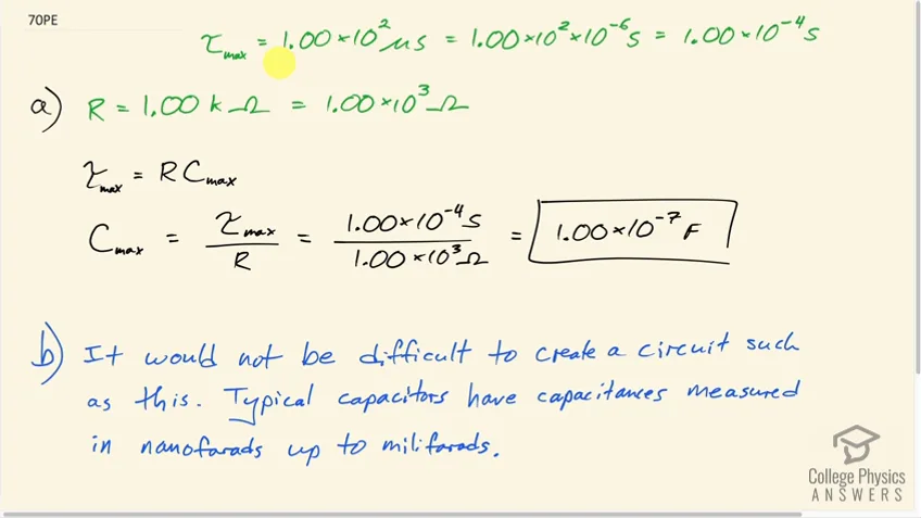 1:26PreviewProblem 70Full video with free trialAn ECG monitor must have an RC time constant less than to be able to measure variations in voltage over small time intervals. (a) If the resistance of the circuit (due mostly to that of the patient’s chest) is $1.00 \textrm{ k}\Omega$ , what is the maximum capacitance of the circuit? (b) Would it be difficult in practice to limit the capacitance to less than the value found in (a)?
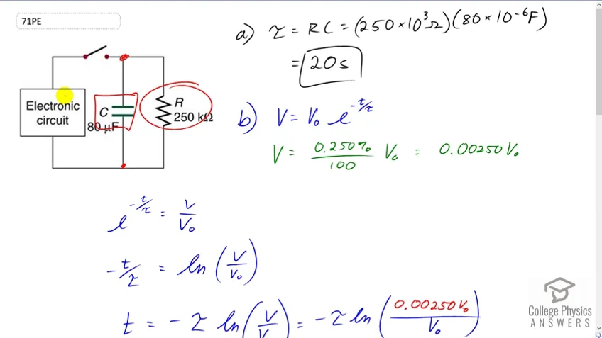 3:57PreviewProblem 71Full video with free trialFigure 21.55 shows how a bleeder resistor is used to discharge a capacitor after an electronic device is shut off, allowing a person to work on the electronics with less risk of shock. (a) What is the time constant? (b) How long will it take to reduce the voltage on the capacitor to 0.250% (5% of 5%) of its full value once discharge begins? (c) If the capacitor is charged to a voltage through a resistance, calculate the time it takes to rise to (This is about two time constants.)
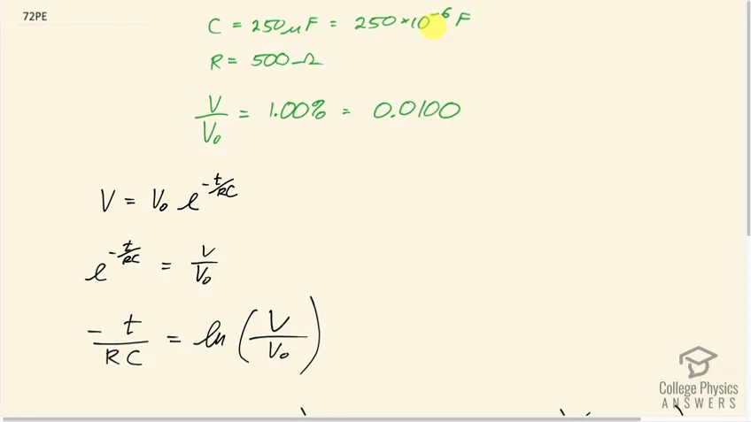 1:19PreviewProblem 72Full video with free trialUsing the exact exponential treatment, find how much time is required to discharge a capacitor through a resistor down to 1.00% of its original voltage.
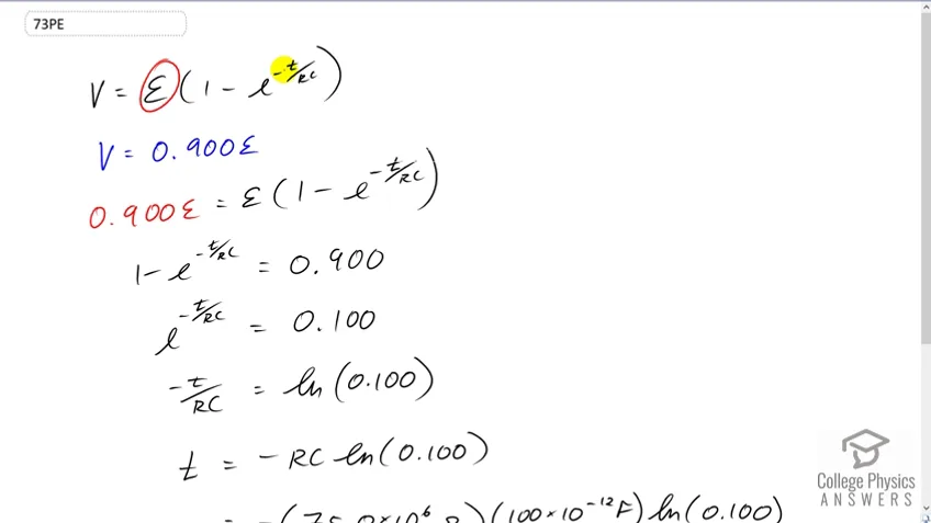 1:37PreviewProblem 73Full video with free trialUsing the exact exponential treatment, find how much time is required to charge an initially uncharged 100-pF capacitor through a resistor to 90.0% of its final voltage.
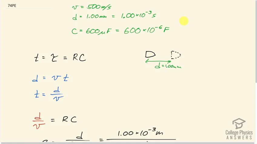 1:34PreviewProblem 74Full video with free trialIf you wish to take a picture of a bullet traveling at 500 m/s, then a very brief flash of light produced by an RC discharge through a flash tube can limit blurring. Assuming 1.00 mm of motion during one RC constant is acceptable, and given that the flash is driven by a capacitor, what is the resistance in the flash tube?
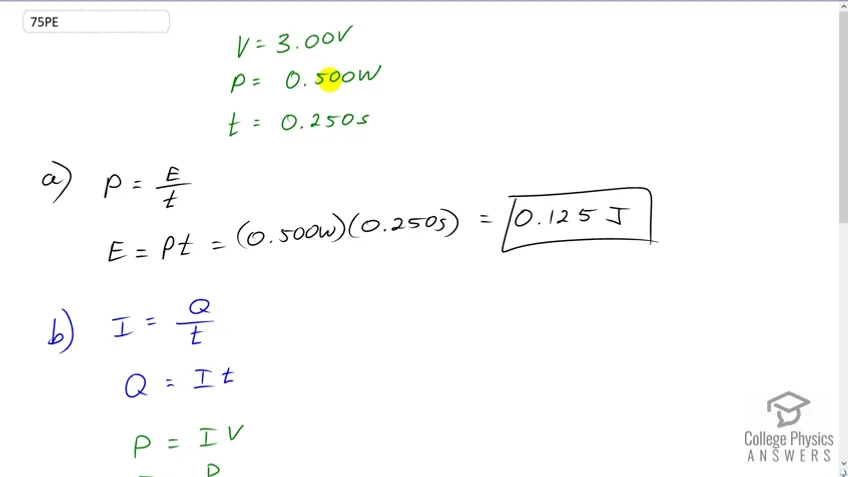 2:28PreviewProblem 75Full video with free trialA flashing lamp in a Christmas earring is based on an discharge of a capacitor through its resistance. The effective duration of the flash is 0.250 s, during which it produces an average 0.500 W from an average 3.00 V. (a) What energy does it dissipate? (b) How much charge moves through the lamp? (c) Find the capacitance. (d) What is the resistance of the lamp?
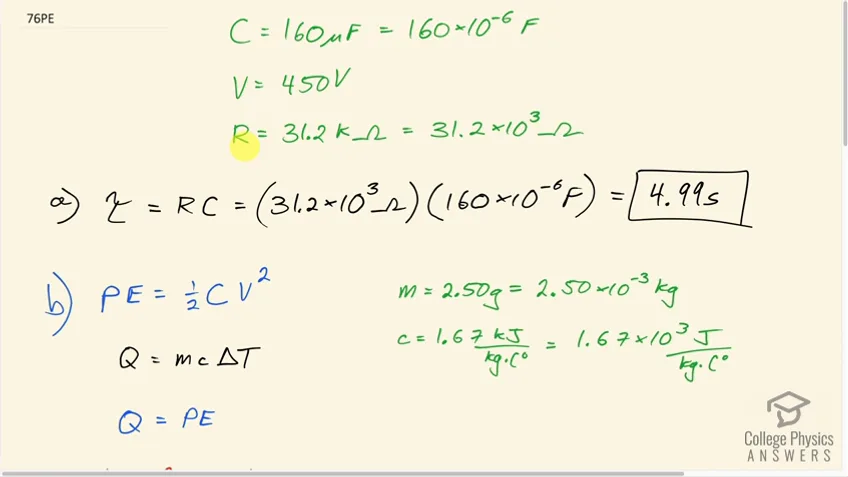 3:44PreviewProblem 76Full video with free trialA capacitor charged to 450 V is discharged through a resistor. (a) Find the time constant. (b) Calculate the temperature increase of the resistor, given that its mass is 2.50 g and its specific heat is , noting that most of the thermal energy is retained in the short time of the discharge. (c) Calculate the new resistance, assuming it is pure carbon. (d) Does this change in resistance seem significant?
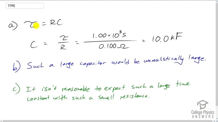 0:39PreviewProblem 77Full video with free trial(a) Calculate the capacitance needed to get an time constant of with a resistor. (b) What is unreasonable about this result? (c) Which assumptions are responsible?
Test Prep for AP® Courses
21.1 Resistors in Series and Parallel
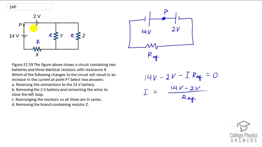 4:16PreviewProblem 1Full video with free trialFigure 21.59 The figure above shows a circuit containing two batteries and three identical resistors with resistance R. Which of the following changes to the circuit will result in an increase in the current at point P? Select two answers. a. Reversing the connections to the 14 V battery. b. Removing the 2 V battery and connecting the wires to close the left loop. c. Rearranging the resistors so all three are in series. d. Removing the branch containing resistor Z.
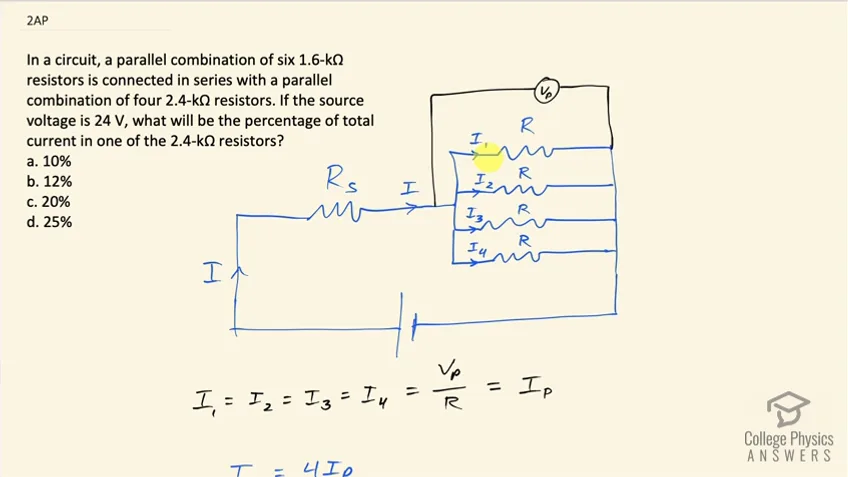 2:07PreviewProblem 2Full video with free trialIn a circuit, a parallel combination of six 1.6-kΩ resistors is connected in series with a parallel combination of four 2.4-kΩ resistors. If the source voltage is 24 V, what will be the percentage of total current in one of the 2.4-kΩ resistors? (a) 10%
(b) 12%
(c) 20%
(d) 25%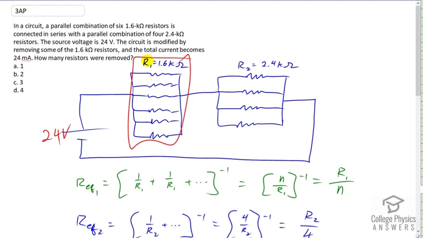 3:16PreviewProblem 3Full video with free trialIn a circuit, a parallel combination of six 1.6-kΩ resistors is connected in series with a parallel combination of four 2.4-kΩ resistors. The source voltage is 24 V. The circuit is modified by removing some of the 1.6 kΩ resistors, and the total current becomes 24 mA. How many resistors were removed? (a) 1
(b) 2
(c) 3
(d) 4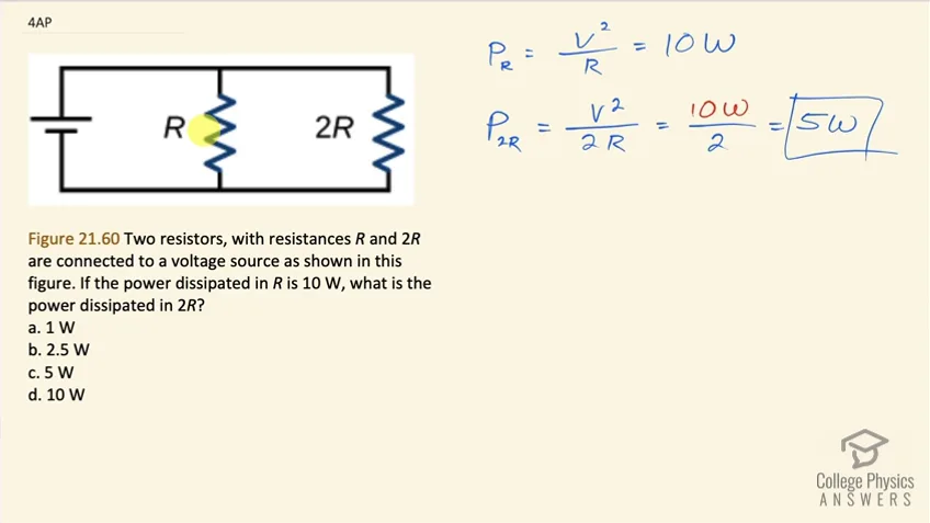 1:06PreviewProblem 4Full video with free trialTwo resistors, with resistances R and 2R are connected to a voltage source as shown in this figure. If the power dissipated in R is 10 W, what is the power dissipated in 2R? (a) 1 W
(b) 2.5 W
(c) 5 W
(d) 10 W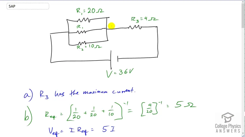 7:10PreviewProblem 5Full video with free trialIn a circuit, a parallel combination of two 20-Ω and one 10-Ω resistors is connected in series with a 4-Ω resistor. The source voltage is 36 V. (a) Find the resistor(s) with the maximum current.
(b) Find the resistor(s) with the maximum voltage drop.
(c) Find the power dissipated in each resistor and hence the total power dissipated in all the resistors. Also find the power output of the source. Are they equal or not? Justify your answer.
(d) Will the answers for questions (a) and (b) differ if a 3 Ω resistor is added in series to the 4 Ω resistor? If yes, repeat the question(s) for the new resistor combination.
(e) If the values of all the resistors and the source voltage are doubled, what will be the effect on the current?
21.2 Electromotive Force: Terminal Voltage
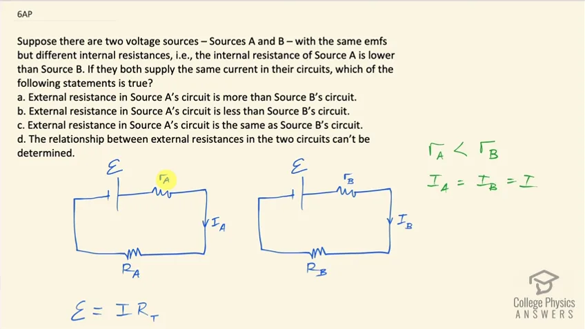 3:30PreviewProblem 6Full video with free trialSuppose there are two voltage sources – Sources A and B – with the same emfs but different internal resistances, i.e., the internal resistance of Source A is lower than Source B. If they both supply the same current in their circuits, which of the following statements is true? (a) External resistance in Source A’s circuit is more than Source B’s circuit.
(b) External resistance in Source A’s circuit is less than Source B’s circuit.
(c) External resistance in Source A’s circuit is the same as Source B’s circuit.
(d) The relationship between external resistances in the two circuits can’t be determined.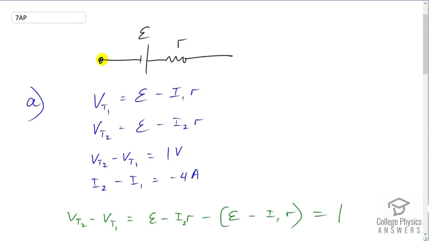 5:34PreviewProblem 7Full video with free trialCalculate the internal resistance of a voltage source if the terminal voltage of the source increases by 1 V when the current supplied decreases by 4 A? Suppose this source is connected in series (in the same direction) to another source with a different voltage but same internal resistance. What will be the total internal resistance? How will the total internal resistance change if the sources are connected in the opposite direction?
21.3 Kirchhoff's Rules
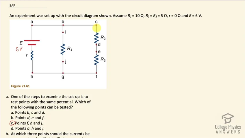 8:54PreviewProblem 8Full video with free trialAn experiment was set up with the circuit diagram shown in Figure 21.61. Assume , , , and . (a) One of the steps to examine the set-up is to test points with the same potential. Which of the following points can be tested? (a) Points b, c and d.
(b) Points d, e and f.
(c) Points f, h and j.
(d) Points a, h and i.
(b) At which three points should the currents be measured so that Kirchhoff’s junction rule can be directly confirmed? (a) Points b, c and d.
(b) Points d, e and f.
(c) Points f, h and j.
(d) Points a, h and i.
(c) If the current in the branch with the voltage source is upward and currents in the other two branches are downward, i.e. Ia = Ii + Ic, identify which of the following can be true? Select two answers. (a) li = Ij - If
(b) Ie = Ih - Ii
(c) Ic = Ij - Ia
(d) Id = Ih - Ij
(d) The measurements reveal that the current through R1 is 0.5 A and R3 is 0.6 A. Based on your knowledge of Kirchoff’s laws, confirm which of the following statements are true. (a) The measured current for R1 is correct but for R3 is incorrect.
(b) The measured current for R3 is correct but for R1 is incorrect.
(c) Both the measured currents are correct.
(d) Both the measured currents are incorrect.
(e) The graph shown in the following Figure 21.62 is the energy dissipated at R1 as a function of time. Which of the following among Figures 21.63 and Figure 21.65 shows the graph for energy dissipated at R2 as a function of time?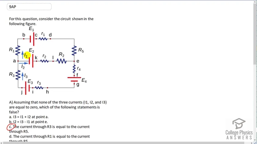 6:37PreviewProblem 9Full video with free trialFor this question, consider the circuit shown in the following figure. (a) Assuming that none of the three currents () are equal to zero, which of the following statements is false? (a)
(b)
(c) The current through is equal to the current through
(d) The current through is equal to the current through
(b) Which of the following statements is true? (a)
(b)
(c)
(d)
(c) If and , which of the following statements is false? (a) The current through will flow from a to b and well be equal to 5 A.
(b) The current through will flow from a to j and will be equal to 2 A.
(c) The current through will flow from d to e and will be equal to 5 A.
(d) None of the above.
(d) If and , will be equal to (a) 3 A
(b) -3 A
(c) 7 A
(d) -7 A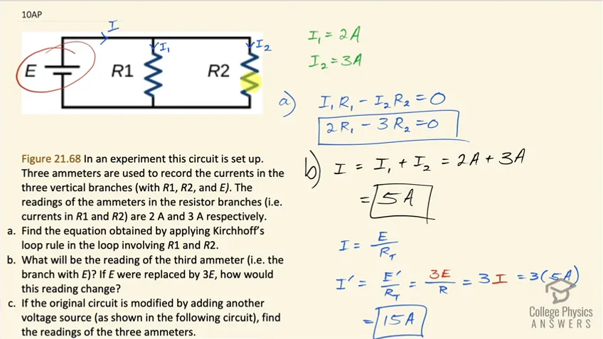 7:45PreviewProblem 10Full video with free trialFigure 21.68 In an experiment this circuit is set up. Three ammeters are used to record the currents in the three vertical branches (with , , and ). The readings of the ammeters in the resistor branches (i.e. currents in and ) are 2 A and 3 A respectively. (a) Find the equation obtained by applying Kirchhoff’s loop rule in the loop involving and .
(b) What will be the reading of the third ammeter (i.e. the branch with E)? If E were replaced by 3E, how would this reading change?
(c) If the original circuit is modified by adding another voltage source (as shown in the following circuit in Figure 21.69), find the readings of the three ammeters.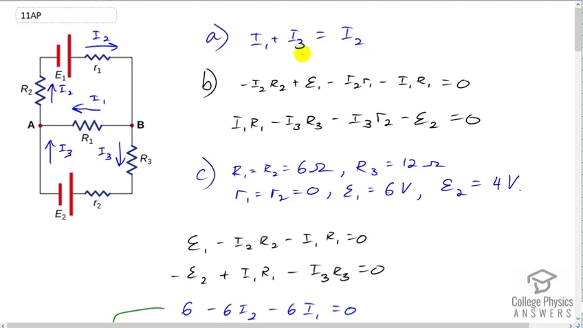 14:16PreviewProblem 11Full video with free trialFigure 21.70 In this circuit, assume the currents through , and are , and respectively and all are flowing in the clockwise direction.
(a) Find the equation obtained by applying Kirchhoff’s junction rule at point A.
(b) Find the equations obtained by applying Kirchhoff’s loop rule in the upper and lower loops.
(c) Assume , , , and . Calculate , and .
(d) For the situation in which is replaced by a closed switch, repeat parts (a) and (b). Using the values for , , , and from part (c) calculate the currents through the three resistors.
(e) For the circuit in part (d) calculate the output power of the voltage source and across all the resistors. Examine if energy is conserved in the circuit.
(f) A student implemented the circuit of part (d) in the lab and measured the current though one of the resistors as 0.19 A. According to the results calculated in part (d) identify the resistor(s). Justify any difference in measured and calculated value.
21.6 DC Circuits Containing Resistors and Capacitors
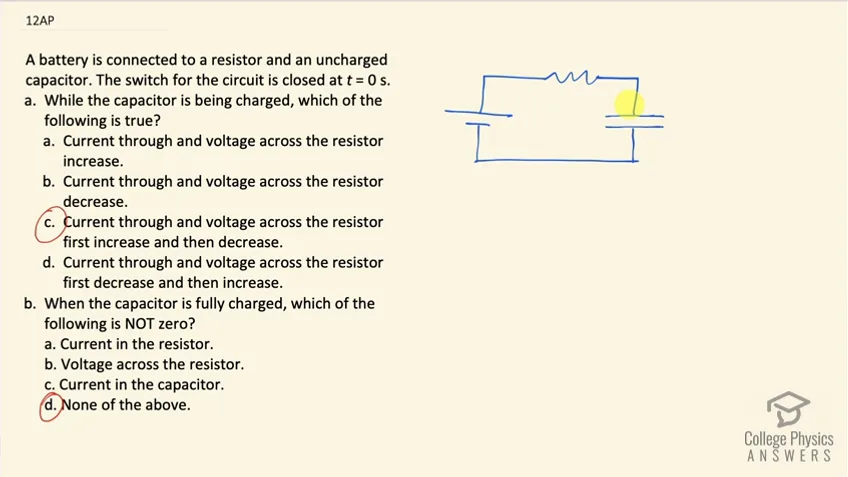 1:44PreviewProblem 12Full video with free trialA battery is connected to a resistor and an uncharged capacitor. The switch for the circuit is closed at t = 0 s. (a) While the capacitor is being charged, which of the following is true? (a) Current through and voltage across the resistor increase.
(b) Current through and voltage across the resistor decrease.
(c) Current through and voltage across the resistor first increase and then decrease.
(d) Current through and voltage across the resistor first decrease and then increase.
(b) When the capacitor is fully charged, which of the following is NOT zero? (a) Current in the resistor.
(b) Voltage across the resistor.
(c) Current in the capacitor.
(d) None of the above.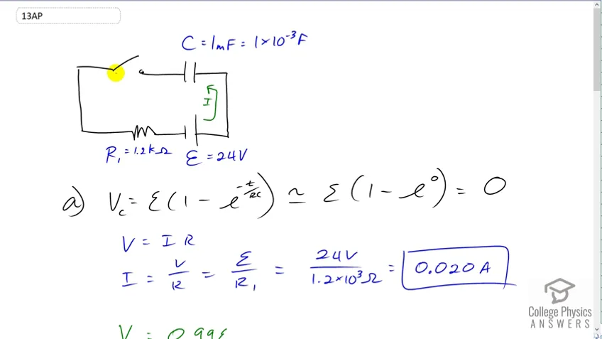 3:57PreviewProblem 13Full video with free trialAn uncharged capacitor is connected in series (with a switch) to a resistor and a voltage source . Assume , and . (a) What will be the current through the circuit as the switch is closed? Draw a circuit diagram and show the direction of current after the switch is closed. How long will it take for the capacitor to be 99% charged?
(b) After full charging, this capacitor is connected in series to another resistor, . What will be the current in the circuit as soon as it’s connected? Draw a circuit diagram and show the direction of current. How long will it take for the capacitor voltage to reach 3.24 V?