Question
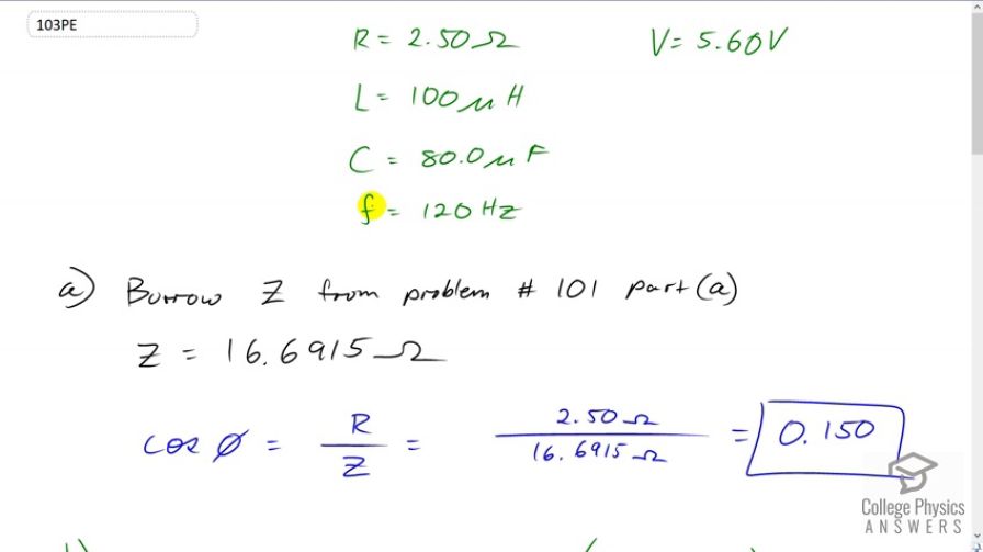
An RLC series circuit has a resistor, a inductor, and an capacitor. (a) Find the power factor at . (b) What is the phase angle at 120 Hz? (c) What is the average power at 120 Hz? (d) Find the average power at the circuit’s resonant frequency.
Final Answer
Solution video
OpenStax College Physics for AP® Courses, Chapter 23, Problem 103 (Problems & Exercises)
vote with a rating of
votes with an average rating of
.
Calculator Screenshots


Video Transcript
This is College Physics Answers with Shaun Dychko. We have an R L C circuit of two and a half ohms, inductance of 100 microHenries, capacitance of 80 microFarads, and the frequency is 120 hertz and the voltage is 5.6 volts. So, Part A asks us to find the power factor for this circuit. And, the power factor is this cos phi. And, we're told that cos phi is resistance divided by impedance. Now, we've seen this circuit in problem 101 and in Part A, we calculated its impedance. And, it had everything the same here, 120 hertz and all the same R L C values. And so, the impedance is 16.6915 ohms. And so, we take the resistance divided by that impedance and we get a power factor of 0.15. The phase angle is going to be the inverse cosine of this power factor. So, the inverse cosine of R over Z. So, that's the inverse cosine of 0.149777, which is 1.42 radiance. I had my calculator in radiant mode when I did this inverse cosine. So, I'm going to multiply that by 180 degrees for every pi radiance to get 81.4 degrees as the phase angle between the voltage and the current. And, the average power dissipated by the circuit will be the RMS current times the RMS voltage multiplied by this power factor. Now, from part C of question 101 for the circuit at the RMS current is 1.5087 amps. And so, we multiply that by the voltage of 5.6 volts times by this power factor that we calculated in part A and we get an average power of 1.27 watts. And now, we're asked to find in part D what is the power dissipated at the resonant frequency? So, at resonant frequency, the impedance equals the resistance since the inductive reactants equals the capacitive reactants. And, we know that impedance is the square root of R squared plus the difference between the inductive reactance and the capacitive reactants square. But when Xl equals Xc, this difference is zero in which case Z equals square root of R squared, which is R. So, that means the power factor cos phi is going to be at its maximum, which is one. And, that's not surprising because we expect that at resonant frequency, we're going to be maximizing the power dissipated. And so, that is the case because this power factor becomes its maximum, which is one. Okay. So, we plug in the number one there and then the RMS current is going to be the RMS voltage divided by impedance. But since the impedance equals the resistance in this case at the resonant frequency, we can substitute R in place of Z. And so, this means the average power dissipated is the RMS voltage times the RMS current, which is the RMS voltage divided by R as we just found here. So, we substitute it for I RMS with that. And the power factor is one, and this makes voltage squared divided by resistance. So, that's 5.6 volts squared divided by two and a half ohms, which is a average power dissipated of 12 and a half watts.