Question
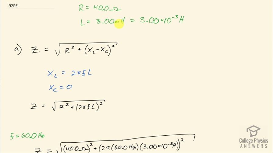
An RL circuit consists of a resistor and a 3.00 mH inductor. (a) Find its impedance Z at 60.0 Hz and 10.0 kHz. (b) Compare these values of Z with those found in Example 23.12 in which there was also a capacitor.
Final Answer
- At 60.0 Hz, the impedance is . At 10.0 kHz, the impedance is
- At 60.0 Hz the impedance in example 23.12 is greater by a factor of 13 on account of having a capacitor of . At 10.0 kHz the impedance in example 23.12 is , which is different by only 2%. This means that adding a capacitor has a significant effect only at low frequencies.
Solution video
OpenStax College Physics for AP® Courses, Chapter 23, Problem 92 (Problems & Exercises)
vote with a rating of
votes with an average rating of
.
Calculator Screenshots


Video Transcript
This is College Physics Answers with Shaun Dychko. A circuit with a resistor of 40.0 ohms and an inductor with inductance of 3.00 millihenries, which is 3.00 times 10 to the minus 3 henries has its impedance—which we will figure out in part (a)— and we'll compare that to the impedance from example [23.12] where they had the same circuit elements, the same resistor and the same inductor but it also had a capacitor of 5.00 microfarads in it and see what change that makes to the impedance values. So impedance is the square root of the resistance squared plus the difference between the inductive reactance and the capacitive reactance squared so you square this difference. The inductive reactance is 2πf times the inductance— f being the frequency— there is no capacitor here so X C is zero and so this means the impedance then is the square root of R squared plus 2πfL all squared. So replacing X L with 2πfL here by the way. (Usually I show that in red don't I? There!) Okay! So at 60 hertz, the impedance then is the square root of 40.0 ohms squared plus 2π times 60.0 hertz times 3.00 times 10 to the minus 3 henries all squared and this works out to 40.0 ohms. At 10.0 kilohertz, the new impedance which we call Z prime is gonna be the square root of 40.0 ohms squared plus 2π times 10.0 times 10 to the 3 hertz times 3.00 times 10 to the minus 3 henries all squared and this is 193 ohms and the impedance increased with frequency as we expected since the inductive reactance increases with increasing frequency. Okay! So example [23.12] has a capacitor added and otherwise, it's the same circuit and at 60.0 hertz, the impedance was 531 ohms so this is greater than the impedance that we measured at 60.0 hertz of 40.0 ohms by a factor of 13 so 531 ohms calculated with this capacitor in the circuit divided by 40.0 ohms that we calculated here in the same circuit minus the capacitor is different by a factor of 13 much more impedance with the capacitor. At 10.0 kilohertz, the impedance was 190 ohms which is nearly the same as what we calculated here differing by only about 2 percent so 193 that we calculated without the capacitor involved minus 90 ohms with the capacitor involved... the 2 percent difference. So this means adding a capacitor has a significant effect only at low frequencies because low frequencies is when capacitive reactance is high and at high frequencies, the capacitive reactance almost has no effect.