Question
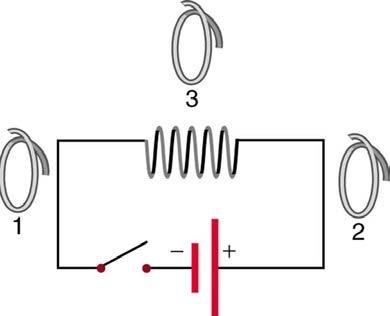
Referring to Figure 23.58, what are the directions of the currents in coils 1, 2, and 3 (assume that the coils are lying in the plane of the circuit): (a) When the switch is first closed? (b) When the switch has been closed for a long time? (c) Just after the switch is opened?

Final Answer
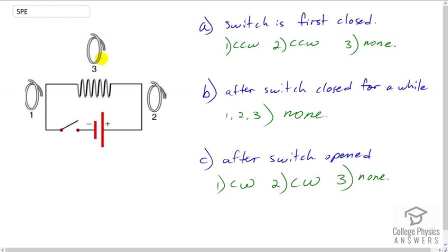
- 1. counter clockwise, 2. counter clockwise, 3. none.
- 1, 2, & 3: none
- 1. clockwise, 2. clockwise, 3. none
Solution video
OpenStax College Physics for AP® Courses, Chapter 23, Problem 5 (Problems & Exercises)

vote with a rating of
votes with an average rating of
.
Video Transcript
This is College Physics Answers with Shaun Dychko. We have a circuit here and these coils here one, two and three are flat: they're in the plane of a circuit. And so, we're looking straight down into this loop here. And, the question is "when the switch is closed, what will be the direction of the induced current in coils one, two and three?" And then, part B: "when the switch has been closed for a long time, what's the induced current?" And then, part C: "after the switch has opened, what direction will the induced current be?" Okay. So in part A, let's consider coil one and the switch has just closed. And so because it's just been closed, the magnetic field strength inside coil one is going from zero, initially, and then it's going to be going up some higher field strength inside. And so, that's going to be... that means that there is a increasing magnetic flux downwards into the page. And that's because the current is gonna be going in this direction coming out of the positive, and going into the negative, and when you grab this wire here with your right hand, your thumb pointing down, you'll be finding that your fingers point down into the page in the middle of this loop. And that's why I've drawn these xs. Now, and so, I'm using red to illustrate the magnetic field due to the wires in this circuit and I'll use green to represent the magnetic field lines created by the induced current in the loop. And so, there's been an increase in flux into the page, and so the induced current will seek to create a magnetic field that opposes that increase into the page, and it'll do so by having magnetic field lines coming out of the page. So these are like arrow points coming out of the page. And in order to create a magnetic field coming out of the page, you have to grab this loop with your right hand and then point your fingers up and out of the page in the middle of the loop and then ask yourself "what direction is your thumb pointing?" And the answer is that it's pointing counterclockwise. Okay. So that's the answer for loop one. Counterclockwise. For loop two, it's having an increased field into the loop, as you can tell by grabbing this portion of the circuit wire with your right hand, and fingers go into the page in the loop (in the middle of the loop) two. And then, loop two will want to create a magnetic field that's induced to oppose this increase by having field lines coming out and it is also going to be a counter-clockwise current -- needed to make field lines coming out of the page in the middle of the loop. So counter clockwise, number two. Number three has no current induced at all because here the circuit wires are going in these circles, and each of them are gonna be producing field lines that are left and right. Well, I guess it's gonna be pointing to the right. If you are to grab this bit of loop here and then point your thumb into the page, you will find that your fingers are pointing to the right. And so because these field lines caused by the looped wires in the circuit are parallel to the plane of loop three, they create no flux at all: these field lines don't cross the plane. There's no magnetic flux even as this field strength is increasing, but the flux inside the loop is not changing because there is no flux. And so, there's no induced current. And that's gonna be true for no matter what the switch is doing. So, that answer is for loop three for part A, B and C. There's never going to be an induced current in it because the field lines will always be parallel to the plane, and there's no flux in other words. Okay. Part B -- so I'm just gonna talk about loops one and two now -- part B, the switch has been closed for a while and so there is current flowing, but the current is not changing. And because it's not changing, the field strength between these loops, one and two, is not changing. And with the field strength not changing, that means the flux is not changing because we're also not squishing the loops or making their geometry change either and so there is no change of flux. So the induced emf is proportional to the rate of change of the flux. Now, even though there is flux, there's no induced current and no induced emf because it's the changing flux that matters. So there's no induced current at all. That's the answer for part B. For part C, when the switch is opened, where we once had lots of field lines going into the page due to the wire and the circuit, we will soon have less and less current... or less and less magnetic field lines in the loop. So now, there was once four, now I suppose there are two. And so, the induced current will want to create magnetic field lines in the middle of the loop that replace what was lost. It's going to oppose the change, in other words. So, the change being the magnetic field or magnetic flux into the loop or into the page is decreasing. And so, it'll try to compensate by keeping it what it once was. And so, the field lines that are induced are going to be into the page and the direction of current will create those direction of field lines is clockwise. And you could tell by grabbing this loop with your right hand and your fingers point into the page in the middle of the loop and your thumb tells you the direction of the induced current, which is clockwise. And for loop two, it's the same story. Whereas, there is once initially lots of field lines into the page, some of them have been taken away because the current is decreasing in the circuit since the switch has been opened, and so the induced current will seek to replace those field lines that were lost and have more field lines going into the page. And to do that, the current that is induced must go clockwise. And there we go.