Chapter 23

Chapter thumbnail
This wind turbine in the Thames Estuary in the UK is an example of induction at work. Wind pushes the blades of the turbine, spinning a shaft attached to magnets. The magnets spin around a conductive coil, inducing an electric current in the coil, and eventually feeding the electrical grid.

Chapter 23 : Electromagnetic Induction, AC Circuits, and Electrical Technologies - all with Video Solutions

Problems & Exercises

Section 23.1: Induced Emf and Magnetic Flux

Section 23.2: Faraday's Law of Induction: Lenz's Law

Problem 3

Referring to Figure 23.57(a), what is the direction of the current induced in coil 2: (a) If the current in coil 1 increases? (b) If the current in coil 1 decreases? (c) If the current in coil 1 is constant? Explicitly show how you follow the steps in the Problem-Solving Strategy for Lenz's Law.

View solution

Problem 4

Referring to Figure 23.57(b), what is the direction of the current induced in the coil: (a) If the current in the wire increases? (b) If the current in the wire decreases? (c) If the current in the wire suddenly changes direction? Explicitly show how you follow the steps in the Problem-Solving Strategy for Lenz’s Law.

View solution

Problem 5

Referring to Figure 23.58, what are the directions of the currents in coils 1, 2, and 3 (assume that the coils are lying in the plane of the circuit): (a) When the switch is first closed? (b) When the switch has been closed for a long time? (c) Just after the switch is opened?

View solution

Problem 6

Referring to Figure 23.58, but reversing the direction of the battery, what are the directions of the currents in coils 1, 2, and 3 (assume that the coils are lying in the plane of the circuit): (a) When the switch is first closed? (b) When the switch has been closed for a long time? (c) Just after the switch is opened?

View solution

Problem 7

Verify that the units of ΔΦΔt\dfrac{\Delta \Phi}{\Delta t} are volts. That is, show that 1Tm2/s=1V1 \textrm{T} \cdot \textrm{m}^2 \textrm{/s} = 1 \textrm{V}

View solution

Problem 8

Suppose a 50-turn coil lies in the plane of the page in a uniform magnetic field that is directed into the page. The coil originally has an area of 0.250 m20.250\textrm{ m}^2 . It is stretched to have no area in 0.100 s. What is the direction and magnitude of the induced emf if the uniform magnetic field has a strength of 1.50 T?

View solution

Problem 9

(a) An MRI technician moves his hand from a region of very low magnetic field strength into an MRI scanner’s 2.00 T field with his fingers pointing in the direction of the field. Find the average emf induced in his wedding ring, given its diameter is 2.20 cm and assuming it takes 0.250 s to move it into the field. (b) Discuss whether this current would significantly change the temperature of the ring.

View solution

Problem 10

An MRI technician moves his hand from a region of very low magnetic field strength into an MRI scanner’s 2.00 T field with his fingers pointing in the direction of the field. Find the average emf induced in his wedding ring, given its diameter is 2.20 cm and assuming it takes 0.250 s to move it into the field. Referring to the situation in the previous problem: (a) What current is induced in the ring if its resistance is 0.0100 Ω0.0100 \textrm{ }\Omega ? (b) What average power is dissipated? (c) What magnetic field is induced at the center of the ring? (d) What is the direction of the induced magnetic field relative to the MRI’s field?

View solution

Problem 11

An emf is induced by rotating a 1000-turn, 20.0 cm diameter coil in the Earth’s 5.00×10⁵ T5.00 \times 10^{-5} \textrm{ T} magnetic field. What average emf is induced, given the plane of the coil is originally perpendicular to the Earth’s field and is rotated to be parallel to the field in 10.0 ms?

View solution

Problem 12

A 0.250 m radius, 500-turn coil is rotated one-fourth of a revolution in 4.17 ms, originally having its plane perpendicular to a uniform magnetic field. (This is 60 rev/s.) Find the magnetic field strength needed to induce an average emf of 10,000 V.

View solution

Problem 13

Approximately how does the emf induced in the loop in Figure 23.57(b) depend on the distance of the center of the loop from the wire?

View solution

Problem 14

(a) A lightning bolt produces a rapidly varying magnetic field. If the bolt strikes the earth vertically and acts like a current in a long straight wire, it will induce a voltage in a loop aligned like that in Figure 23.57(b). What voltage is induced in a 1.00 m diameter loop 50.0 m from a 2.00×10⁶ A2.00\times 10^{6}\textrm{ A} lightning strike, if the current falls to zero in 25.0 μs25.0\textrm{ }\mu\textrm{s} ? (b) Discuss circumstances under which such a voltage would produce noticeable consequences.

View solution

Section 23.3: Motional Emf

Problem 15

Use Faraday’s law, Lenz’s law, and RHR-1 to show that the magnetic force on the current in the moving rod in Figure 23.11 is in the opposite direction of its velocity.

View solution

Problem 16

If a current flows in the Satellite Tether shown in Figure 23.12, use Faraday’s law, Lenz’s law, and RHR-1 to show that there is a magnetic force on the tether in the direction opposite to its velocity.

View solution

Problem 17

(a) A jet airplane with a 75.0 m wingspan is flying at 280 m/s. What emf is induced between wing tips if the vertical component of the Earth’s field is 3.00×10⁵ T3.00 \times 10^{-5} \textrm{ T}? (b) Is an emf of this magnitude likely to have any consequences? Explain.

View solution

Problem 18

(a) A nonferrous screwdriver is being used in a 2.00 T magnetic field. What maximum emf can be induced along its 12.0 cm length when it moves at 6.00 m/s? (b) Is it likely that this emf will have any consequences or even be noticed?

View solution

Problem 19

At what speed must the sliding rod in Figure 23.11 move to produce an emf of 1.00 V in a 1.50 T field, given the rod’s length is 30.0 cm?

View solution

Problem 21

Prove that when BB, ll, and vv are not mutually perpendicular, motional EMF is given by EMF=Blvsin(θ)EMF = Blv\sin(\theta). If vv is perpendicular to BB, then θ\theta is the angle between ll and BB. If ll is perpendicular to BB, then θ\theta is the angle between vv and BB.

View solution

Problem 22

In the August 1992 space shuttle flight, only 250 m of the conducting tether considered in Example 23.2 could be let out. A 40.0 V motional emf was generated in the Earth’s 5.00×10⁵ T5.00\times 10^{-5}\textrm{ T} field, while moving at 7.80×10³ m/s7.80\times 10^{3}\textrm{ m/s} . What was the angle between the shuttle’s velocity and the Earth’s field, assuming the conductor was perpendicular to the field?

View solution

Problem 23

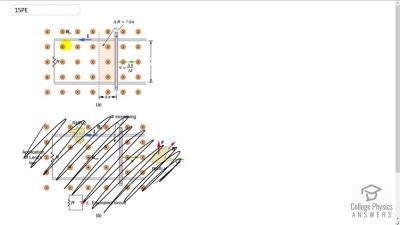
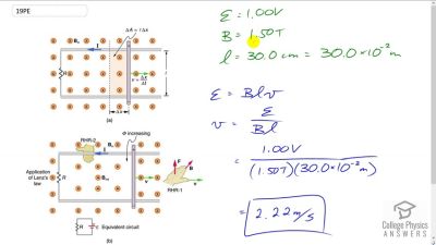
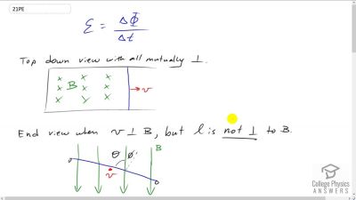
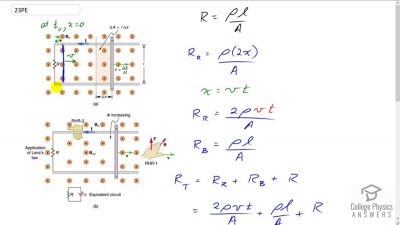
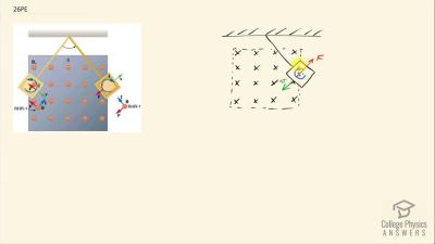
Derive an expression for the current in a system like that in Figure 23.11, under the following conditions. The resistance between the rails is RR , the rails and the moving rod are identical in cross section AA and have the same resistivity ρ\rho . The distance between the rails is ll, and the rod moves at constant speed vv perpendicular to the uniform field BB. At time zero, the moving rod is next to the resistance RR.

View solution

Problem 24

The Tethered Satellite in Figure 23.12 has a mass of 525 kg and is at the end of a 20.0 km long, 2.50 mm diameter cable with the tensile strength of steel. (a) How much does the cable stretch if a 100 N force is exerted to pull the satellite in? (Assume the satellite and shuttle are at the same altitude above the Earth.) (b) What is the effective force constant of the cable? (c) How much energy is stored in it when stretched by the 100 N force?

View solution

Problem 25

The Tethered Satellite discussed in this module is producing 5.00 kV, and a current of 10.0 A flows. (a) What magnetic drag force does this produce if the system is moving at 7.80 km/s? (b) How much kinetic energy is removed from the system in 1.00 h, neglecting any change in altitude or velocity during that time? (c) What is the change in velocity if the mass of the system is 100,000 kg? (d) Discuss the long term consequences (say, a week-long mission) on the space shuttle’s orbit, noting what effect a decrease in velocity has and assessing the magnitude of the effect.

View solution

Section 23.4: Eddy Currents and Magnetic Damping

Problem 26

Make a drawing similar to Figure 23.14, but with the pendulum moving in the opposite direction. Then use Faraday’s law, Lenz’s law, and RHR-1 to show that magnetic force opposes motion.

View solution

Problem 27

A coil is moved through a magnetic field as shown in Figure 23.59. The field is uniform inside the rectangle and zero outside. What is the direction of the induced current and what is the direction of the magnetic force on the coil at each position shown?

View solution

Section 23.5: Electric Generators

Problem 29

At what angular velocity in rpm will the peak voltage of a generator be 480 V, if its 500-turn, 8.00 cm diameter coil rotates in a 0.250 T field?

View solution

Problem 30

What is the peak emf generated by rotating a 1000-turn, 20.0 cm diameter coil in the Earth’s 5.00×10⁵ T5.00\times 10^{-5}\textrm{ T} magnetic field, given the plane of the coil is originally perpendicular to the Earth’s field and is rotated to be parallel to the field in 10.0 ms?

View solution

Problem 31

What is the peak emf generated by a 0.250 m radius, 500-turn coil is rotated one-fourth of a revolution in 4.17 ms, originally having its plane perpendicular to a uniform magnetic field of strength 0.425 T. (This is 60 rev/s.)

View solution

Problem 32

(a) A bicycle generator rotates at 1875 rad/s, producing an 18.0 V peak emf. It has a 1.00 by 3.00 cm rectangular coil in a 0.640 T field. How many turns are in the coil? (b) Is this number of turns of wire practical for a 1.00 by 3.00 cm coil?

View solution

Problem 33

This problem refers a the bicycle generator which has a 1.00 by 3.00 cm rectangular coil and 50 turns. It is driven by a 1.60 cm diameter wheel that rolls on the outside rim of the bicycle tire. (a) What is the velocity of the bicycle if the generator’s angular velocity is 1875 rad/s? (b) What is the maximum emf of the generator when the bicycle moves at 10.0 m/s, noting that it was 18.0 V under the original conditions? (c) If the sophisticated generator can vary its own magnetic field, what field strength will it need at 5.00 m/s to produce a 9.00 V maximum emf?

View solution

Problem 34

(a) A car generator turns at 400 rpm when the engine is idling. Its 300-turn, 5.00 by 8.00 cm rectangular coil rotates in an adjustable magnetic field so that it can produce sufficient voltage even at low rpms. What is the field strength needed to produce a 24.0 V peak emf? (b) Discuss how this required field strength compares to those available in permanent and electromagnets.

View solution

Problem 35

Show that if a coil rotates at an angular velocity ω\omega , the period of its AC output is 2πω\dfrac{2 \pi}{\omega}.

View solution

Problem 36

A 75-turn, 10.0 cm diameter coil rotates at an angular velocity of 8.00 rad/s in a 1.25 T field, starting with the plane of the coil parallel to the field. (a) What is the peak emf? (b) At what time is the peak emf first reached? (c) At what time is the emf first at its most negative? (d) What is the period of the AC voltage output?

View solution

Problem 37

(a) If the emf of a coil rotating in a magnetic field is zero at t=0t = 0, and increases to its first peak at t=0.100 mst = 0.100 \textrm{ ms}, what is the angular velocity of the coil? (b) At what time will its next maximum occur? (c) What is the period of the output? (d) When is the output first one-fourth of its maximum? (e) When is it next one-fourth of its maximum?

View solution

Problem 38

A 500-turn coil with a 0.250 m20.250\textrm{ m}^2 area is spun in the Earth's 5.00×10⁵ T5.00\times 10^{-5}\textrm{ T} field, producing a 12.0 kV maximum emf. (a) At what angular velocity must the coil be spun? (b) What is unreasonable about this result? (c) Which assumption or premise is responsible?

View solution

Section 23.6: Back Emf

Problem 39

Suppose a motor connected to a 120 V source draws 10.0 A when it first starts. (a) What is its resistance? (b) What current does it draw at its normal operating speed when it develops a 100 V back emf?

View solution

Problem 40

A motor operating on 240 V electricity has a 180 V back emf at operating speed and draws a 12.0 A current. (a) What is its resistance? (b) What current does it draw when it is first started?

View solution

Problem 42

The motor in a toy car operates on 6.00 V, developing a 4.50 V back emf at normal speed. If it draws 3.00 A at normal speed, what current does it draw when starting?

View solution

Problem 43

The motor in a toy car is powered by four batteries in series, which produce a total emf of 6.00 V. The motor draws 3.00 A and develops a 4.50 V back emf at normal speed. Each battery has a 0.100Ω0.100 \Omega internal resistance. What is the resistance of the motor?

View solution

Section 23.7: Transformers

Problem 44

A plug-in transformer, like that in Figure 23.29, supplies 9.00 V to a video game system. (a) How many turns are in its secondary coil, if its input voltage is 120 V and the primary coil has 400 turns? (b) What is its input current when its output is 1.30 A?

View solution

Problem 45

An American traveler in New Zealand carries a transformer to convert New Zealand’s standard 240 V to 120 V so that she can use some small appliances on her trip. (a) What is the ratio of turns in the primary and secondary coils of her transformer? (b) What is the ratio of input to output current? (c) How could a New Zealander traveling in the United States use this same transformer to power her 240 V appliances from 120 V?

View solution

Problem 46

A cassette recorder uses a plug-in transformer to convert 120 V to 12.0 V, with a maximum current output of 200 mA. (a) What is the current input? (b) What is the power input? (c) Is this amount of power reasonable for a small appliance?

View solution

Problem 47

(a) What is the voltage output of a transformer used for rechargeable flashlight batteries, if its primary has 500 turns, its secondary 4 turns, and the input voltage is 120 V? (b) What input current is required to produce a 4.00 A output? (c) What is the power input?

View solution

Problem 48

(a) The plug-in transformer for a laptop computer puts out 7.50 V and can supply a maximum current of 2.00 A. What is the maximum input current if the input voltage is 240 V? Assume 100% efficiency. (b) If the actual efficiency is less than 100%, would the input current need to be greater or smaller? Explain.

View solution

Problem 49

A multipurpose transformer has a secondary coil with several points at which a voltage can be extracted, giving outputs of 5.60, 12.0, and 480 V. (a) The input voltage is 240 V to a primary coil of 280 turns. What are the numbers of turns in the parts of the secondary used to produce the output voltages? (b) If the maximum input current is 5.00 A, what are the maximum output currents (each used alone)?

View solution

Problem 50

A large power plant generates electricity at 12.0 kV. Its old transformer once converted the voltage to 335 kV. The secondary of this transformer is being replaced so that its output can be 750 kV for more efficient cross-country transmission on upgraded transmission lines. (a) What is the ratio of turns in the new secondary compared with the old secondary? (b) What is the ratio of new current output to old output (at 335 kV) for the same power? (c) If the upgraded transmission lines have the same resistance, what is the ratio of new line power loss to old?

View solution

Problem 51

If the power output in the previous problem is 1000 MW and line resistance is 2.00Ω2.00 \Omega, what were the old and new line losses?

View solution

Problem 52

The 335 kV AC electricity from a power transmission line is fed into the primary coil of a transformer. The ratio of the number of turns in the secondary to the number in the primary is NsNp=1000\dfrac{\textrm{N}_\textrm{s}}{\textrm{N}_\textrm{p}} = 1000 . (a) What voltage is induced in the secondary? (b) What is unreasonable about this result? (c) Which assumption or premise is responsible?

View solution

Section 23.8: Electrical Safety: Systems and Devices

Problem 54

A short circuit to the grounded metal case of an appliance occurs as shown in Figure 23.60. The person touching the case is wet and only has a 3.00 kΩ3.00\textrm{ k}\Omega resistance to earth/ ground. (a) What is the voltage on the case if 5.00 mA flows through the person? (b) What is the current in the short circuit if the resistance of the earth/ground wire is 0.200 Ω0.200\textrm{ }\Omega ? (c) Will this trigger the 20.0 A circuit breaker supplying the appliance?

View solution

Section 23.9: Inductance

Problem 55

Two coils are placed close together in a physics lab to demonstrate Faraday’s law of induction. A current of 5.00 A in one is switched off in 1.00 ms, inducing a 9.00 V emf in the other. What is their mutual inductance?

View solution

Problem 56

If two coils placed next to one another have a mutual inductance of 5.00 mH, what voltage is induced in one when the 2.00 A current in the other is switched off in 30.0 ms?

View solution

Problem 58

A device is turned on and 3.00 A flows through it 0.100 ms later. What is the self-inductance of the device if an induced 150 V emf opposes this?

View solution

Problem 59

Starting with EMF2=MΔI1ΔtEMF_2 = -M \dfrac{\Delta I_1}{\Delta t}, show that the units of inductance are VsA=Ωs\dfrac{\textrm{V} \cdot \textrm{s}}{\textrm{A}} = \Omega \cdot \textrm{s}

View solution

Problem 60

Camera flashes charge a capacitor to high voltage by switching the current through an inductor on and off rapidly. In what time must the 0.100 A current through a 2.00 mH inductor be switched on or off to induce a 500 V emf?

View solution

Problem 61

A large research solenoid has a self-inductance of 25.0 H. (a) What induced emf opposes shutting it off when 100 A of current through it is switched off in 80.0 ms? (b) How much energy is stored in the inductor at full current? (c) At what rate in watts must energy be dissipated to switch the current off in 80.0 ms? (d) In view of the answer to the last part, is it surprising that shutting it down this quickly is difficult?

View solution

Problem 62

(a) Calculate the self-inductance of a 50.0 cm long, 10.0 cm diameter solenoid having 1000 loops. (b) How much energy is stored in this inductor when 20.0 A of current flows through it? (c) How fast can it be turned off if the induced emf cannot exceed 3.00 V?

View solution

Problem 63

A precision laboratory resistor is made of a coil of wire 1.50 cm in diameter and 4.00 cm long, and it has 500 turns. (a) What is its self-inductance? (b) What average emf is induced if the 12.0 A current through it is turned on in 5.00 ms (one-fourth of a cycle for 50 Hz AC)? (c) What is its inductance if it is shortened to half its length and counter- wound (two layers of 250 turns in opposite directions)?

View solution

Problem 64

The heating coils in a hair dryer are 0.800 cm in diameter, have a combined length of 1.00 m, and a total of 400 turns. (a) What is their total self-inductance assuming they act like a single solenoid? (b) How much energy is stored in them when 6.00 A flows? (c) What average emf opposes shutting them off if this is done in 5.00 ms (one-fourth of a cycle for 50 Hz AC)?

View solution

Problem 65

When the 20.0 A current through an inductor is turned off in 1.50 ms, an 800 V emf is induced, opposing the change. What is the value of the self-inductance?

View solution

Problem 67

A very large, superconducting solenoid such as one used in MRI scans, stores 1.00 MJ of energy in its magnetic field when 100 A flows. (a) Find its self-inductance. (b) If the coils “go normal,” they gain resistance and start to dissipate thermal energy. What temperature increase is produced if all the stored energy goes into heating the 1000 kg magnet, given its average specific heat is 200 J/kgC200 \textrm{ J/kg}\cdot\textrm{C}^\circ?

View solution

Problem 68

A 25.0 H inductor has 100 A of current turned off in 1.00 ms. (a) What voltage is induced to oppose this? (b) What is unreasonable about this result? (c) Which assumption or premise is responsible?

View solution

Section 23.10: RL Circuits

Problem 69

If you want a characteristic RL time constant of 1.00 s, and you have a 500Ω500 \Omega resistor, what value of self- inductance is needed?

View solution

Problem 70

Your RL circuit has a characteristic time constant of 20.0 ns, and a resistance of 5.00 MΩ5.00\textrm{ M}\Omega . (a) What is the inductance of the circuit? (b) What resistance would give you a 1.00 ns time constant, perhaps needed for quick response in an oscilloscope?

View solution

Problem 71

A large superconducting magnet, used for magnetic resonance imaging, has a 50.0 H inductance. If you want current through it to be adjustable with a 1.00 s characteristic time constant, what is the minimum resistance of system?

View solution

Problem 73

Suppose you have a supply of inductors ranging from 1.00 nH to 10.0 H, and resistors ranging from 0.100 Ω0.100 \textrm{ }\Omega to 1.00 MΩ1.00 \textrm{ M}\Omega. What is the range of characteristic RL time constants you can produce by connecting a single resistor to a single inductor?

View solution

Problem 74

(a) What is the characteristic time constant of a 25.0 mH inductor that has a resistance of 4.00 Ω4.00\textrm{ }\Omega ? (b) If it is connected to a 12.0 V battery, what is the current after 12.5 ms?

View solution

Problem 75

What percentage of the final current IoI_o flows through an inductor LL in series with a resistor RR, three time constants after the circuit is completed?

View solution

Problem 76

The 5.00 A current through a 1.50 H inductor is dissipated by a 2.00 Ω2.00\textrm{ }\Omega resistor in a circuit like that in Figure 23.44 with the switch in position 2. (a) What is the initial energy in the inductor? (b) How long will it take the current to decline to 5.00% of its initial value? (c) Calculate the average power dissipated, and compare it with the initial power dissipated by the resistor.

View solution

Problem 77

(a) Use the exact exponential treatment to find how much time is required to bring the current through an 80.0 mH inductor in series with a 15.0 Ω15.0 \textrm{ }\Omega resistor to 99.0% of its final value, starting from zero. (b) Compare your answer to the approximate treatment using integral numbers of τ\tau. (c) Discuss how significant the difference is.

View solution

Problem 78

(a) Using the exact exponential treatment, find the time required for the current through a 2.00 H inductor in series with a 0.500 Ω0.500\textrm{ }\Omega resistor to be reduced to 0.100% of its original value. (b) Compare your answer to the approximate treatment using integral numbers of τ\tau . (c) Discuss how significant the difference is.

View solution

Section 23.11: Reactnce, Inductive and Capacitive

Problem 80

What value of inductance should be used if a 20.0 kΩ20.0\textrm{ k}\Omega reactance is needed at a frequency of 500 Hz?

View solution

Problem 83

(a) Find the current through a 0.500 H inductor connected to a 60.0 Hz, 480 V AC source. (b) What would the current be at 100 kHz?

View solution

Problem 84

(a) What current flows when a 60.0 Hz, 480 V AC source is connected to a 0.250 μF0.250\textrm{ }\mu\textrm{F} capacitor? (b) What would the current be at 25.0 kHz?

View solution

Problem 87

(a) An inductor designed to filter high-frequency noise from power supplied to a personal computer is placed in series with the computer. What minimum inductance should it have to produce a 2.00 kΩ2.00 \textrm{ k}\Omega reactance for 15.0 kHz noise? (b) What is its reactance at 60.0 Hz?

View solution

Problem 88

The capacitor in Figure 23.55(a) is designed to filter low- frequency signals, impeding their transmission between circuits. (a) What capacitance is needed to produce a 100 kΩ100\textrm{ k}\Omega reactance at a frequency of 120 Hz? (b) What would its reactance be at 1.00 MHz? (c) Discuss the implications of your answers to (a) and (b).

View solution

Problem 89

The capacitor in Figure 23.55(b) will filter high-frequency signals by shorting them to earth/ground. (a) What capacitance is needed to produce a reactance of 10.0 mΩ10.0 \textrm{ m}\Omega for a 5.00 kHz signal? (b) What would its reactance be at 3.00 Hz? (c) Discuss the implications of your answers to (a) and (b).

View solution

Problem 90

In a recording of voltages due to brain activity (an EEG), a 10.0 mV signal with a 0.500 Hz frequency is applied to a capacitor, producing a current of 100 mA. Resistance is negligible. (a) What is the capacitance? (b) What is unreasonable about this result? (c) Which assumption or premise is responsible?

View solution

Section 23.12: RLC Series and AC Circuits

Problem 92

An RL circuit consists of a 40.0 Ω40.0\textrm{ }\Omega resistor and a 3.00 mH inductor. (a) Find its impedance Z at 60.0 Hz and 10.0 kHz. (b) Compare these values of Z with those found in Example 23.12 in which there was also a capacitor.

View solution

Problem 93

An RC circuit consists of a 40.0 Ω40.0 \textrm{ }\Omega resistor and a 5.00 μF5.00 \textrm{ }\mu \textrm{F} capacitor. (a) Find its impedance at 60.0 Hz and 10.0 kHz. (b) Compare these values of ZZ with those found in Example 23.12, in which there was also an inductor.

View solution

Problem 94

An LC circuit consists of a 3.00 mH inductor and a 5.00 μF5.00\textrm{ }\mu\textrm{F} capacitor. (a) Find its impedance at 60.0 Hz and 10.0 kHz. (b) Compare these values of Z with those found in Example 23.12 in which there was also a resistor.

View solution

Problem 96

To receive AM radio, you want an RLC circuit that can be made to resonate at any frequency between 500 and 1650 kHz. This is accomplished with a fixed 1.00 μH1.00\textrm{ }\mu\textrm{H} inductor connected to a variable capacitor. What range of capacitance is needed?

View solution

Problem 97

Suppose you have a supply of inductors ranging from 1.00 nH to 10.0 H, and capacitors ranging from 1.00 pF to 0.100 F. What is the range of resonant frequencies that can be achieved from combinations of a single inductor and a single capacitor?

View solution

Problem 99

What inductance do you need to produce a resonant frequency of 60.0 Hz, when using a 2.00 μF2.00 \textrm{ }\mu \textrm{F} capacitor?

View solution

Problem 100

The lowest frequency in the FM radio band is 88.0 MHz. (a) What inductance is needed to produce this resonant frequency if it is connected to a 2.50 pF capacitor? (b) The capacitor is variable, to allow the resonant frequency to be adjusted to as high as 108 MHz. What must the capacitance be at this frequency?

View solution

Problem 101

An RLC series circuit has a 2.50 Ω2.50 \textrm{ }\Omega resistor, a 100 μH100 \textrm{ }\mu \textrm{H} inductor, and an 80.0 μF80.0 \textrm{ }\mu \textrm{F} capacitor.(a) Find the circuit’s impedance at 120 Hz. (b) Find the circuit’s impedance at 5.00 kHz. (c) If the voltage source has Vrms=5.60 VV_{\textrm{rms}} = 5.60 \textrm{ V}, what is IrmsI_{\textrm{rms}} at each frequency? (d) What is the resonant frequency of the circuit? (e) What is IrmsI_{\textrm{rms}} at resonance?

View solution

Problem 102

An RLC series circuit has a 1.00 kΩ1.00\textrm{ k}\Omega resistor, a 150 μH150\textrm{ }\mu\textrm{H} inductor, and a 25.0 nF capacitor. (a) Find the circuit’s impedance at 500 Hz. (b) Find the circuit’s impedance at 7.50 kHz. (c) If the voltage source has Vrms=408 V\textrm{V}_\textrm{rms}=408\textrm{ V} , what is Irms\textrm{I}_\textrm{rms} at each frequency? (d) What is the resonant frequency of the circuit? (e) What is Irms\textrm{I}_\textrm{rms} at resonance?

View solution

Problem 103

An RLC series circuit has a 2.50 Ω2.50 \textrm{ }\Omega resistor, a 100 μH100 \textrm{ }\mu \textrm{H} inductor, and an 80.0 μF80.0 \textrm{ }\mu \textrm{F} capacitor. (a) Find the power factor at f=120 Hzf = 120 \textrm{ Hz}. (b) What is the phase angle at 120 Hz? (c) What is the average power at 120 Hz? (d) Find the average power at the circuit’s resonant frequency.

View solution

Problem 104

An RLC series circuit has a 1.00 kΩ1.00\textrm{ k}\Omega resistor, a 150 μH150\textrm{ }\mu\textrm{H} inductor, and a 25.0 nF25.0\textrm{ nF} capacitor. (a) Find the power factor at f = 7.50 Hz . (b) What is the phase angle at this frequency? (c) What is the average power at this frequency? (d) Find the average power at the circuit’s resonant frequency.

View solution

Problem 105

An RLC series circuit has a 200 Ω200 \textrm{ }\Omega resistor and a 25.0 mH inductor. At 8000 Hz, the phase angle is 45.045.0^\circ. (a) What is the impedance? (b) Find the circuit’s capacitance. (c) If Vrms=408 VV_{\textrm{rms}} = 408 \textrm{ V} is applied, what is the average power supplied?

View solution

Test Prep for AP® Courses

Section 23.1: Induced Emf and Magnetic Flux

Problem 1 (AP)

To produce current with a coil and bar magnet you can:
  1. move the coil but not the magnet.
  2. move the magnet but not the coil.
  3. move either the coil or the magnet.
  4. It is not possible to produce current.

View solution

Problem 2 (AP)

Calculate the magnetic flux for a coil of area 0.2 m20.2\textrm{ m}^2 placed at an angle of θ=60\theta=60^\circ to a magnetic field of strength 1.5×10³ T1.5\times 10^{-3}\textrm{ T}. At what angle will the flux be at its maximum?

View solution

Section 23.5: Electric Generators

Problem 3 (AP)

The emf induced in a coil that is rotating in a magnetic field will be at a maximum when
  1. the magnetic flux is at a maximum.
  2. the magnetic flux is at a minimum.
  3. the change in magnetic flux is at a maximum.
  4. the change in magnetic flux is at a minimum.

View solution

Problem 4 (AP)

A coil with circular cross section and 20 turns is rotating at a rate of 400 rpm between the poles of a magnet. If the magnetic field strength is 0.6 T and peak voltage is 0.2 V, what is the radius of the coil? If the emf of the coil is zero at t = 0 s, when will it reach its peak emf?

View solution

Section 23.7: Transformers

Problem 5 (AP)

Which of the following statements is true for a step-down transformer? Select two answers.
  1. Primary voltage is higher than secondary voltage.
  2. Primary voltage is lower than secondary voltage.
  3. Primary current is higher than secondary current.
  4. Primary current is lower than secondary current.

View solution

Problem 6 (AP)

An ideal step-up transformer with turn ratio 1:30 is supplied with an input power of 120 W. If the output voltage is 210 V, calculate the output power and input current.

View solution

Section 23.8: Electrical Safety: Systems and Devices

Problem 7 (AP)

Which of the following statements is true for an isolation transformer?
  1. It has more primary turns than secondary turns.
  2. It has fewer primary turns than secondary turns.
  3. It has an equal number of primary and secondary turns.
  4. It can have more, fewer, or an equal number of primary and secondary turns.

View solution