Question
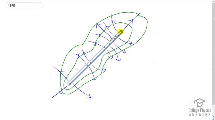
(a) Sketch the electric field lines in the vicinity of the charged insulator in Figure 19.37. Note its non-uniform charge distribution. (b) Sketch equipotential lines surrounding the insulator. Indicate the direction of increasing potential.
Final Answer
Please see the solution video.
Solution video
OpenStax College Physics for AP® Courses, Chapter 19, Problem 43 (Problems & Exercises)
vote with a rating of
votes with an average rating of
.
Video Transcript
This is College Physics Answers with Shaun Dychko. We begin by drawing electric field lines which are arrows pointing away from these positive charges and the field lines would be drawn closer together where the charges have a greater density and at this position here which is sort of at the end of the this clump of positive charges, the field lines would tend to bend away from that clump and whereas from this clump, in this end, the field lines would tend to bend away from that clump and then there is not many field lines in between because there are no charges in between and then after we are done drawing the field lines, we make the equipotential lines by going at right angles to the field lines and so because this clump is curving away, like that, this equipotential lines sort of bends closer to the rod and then bends away from the rod and then so on and here we go.