Question
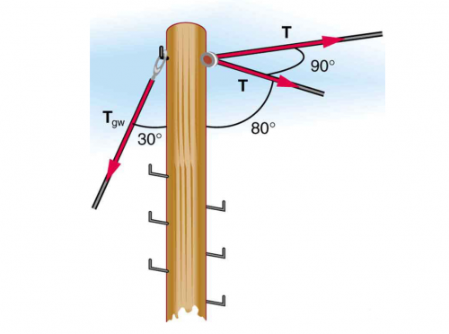
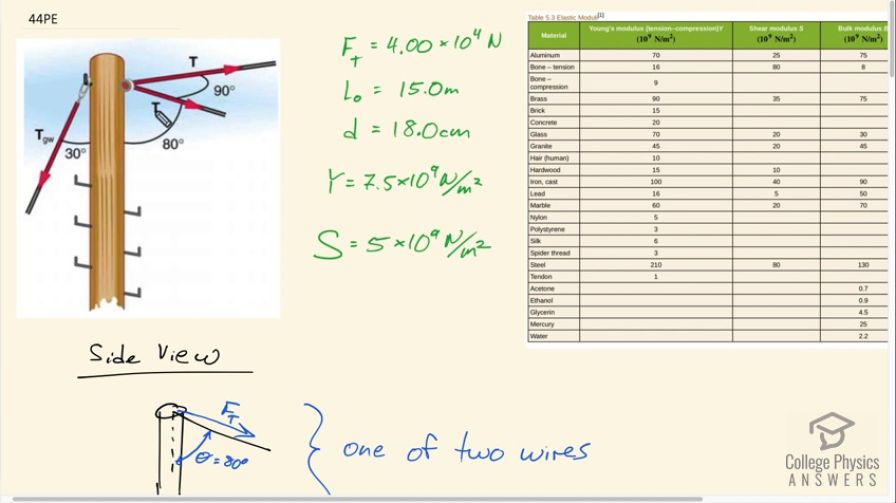
The pole in Figure 5.22 is at a bend in a power line and is therefore subjected to more shear force than poles in straight parts of the line. The tension in each line is , at the angles shown. The pole is 15.0 m tall, has an 18.0 cm diameter, and can be considered to have half the stiffness of hardwood. (a) Calculate the compression of the pole. (b) Find how much it bends and in what direction. (c) Find the tension in a guy wire used to keep the pole straight if it is attached to the top of the pole at an angle of with the vertical. (Clearly, the guy wire must be in the opposite direction of the bend.)
Final Answer
- along the acute angle bisector between the power lines
Solution video
OpenStax College Physics, Chapter 5, Problem 44 (Problems & Exercises)
vote with a rating of
votes with an average rating of
.
Calculator Screenshots


Video Transcript
This is College Physics Answers with Shaun Dychko. A power pole has two power lines connected to it and there's a 90-degree angle here between these power lines. The lines are at an angle of 80 degrees with respect to the pole. This guy-wire is part of part C in this question, but initially we imagined that there's no guy-wire connected to the ground. For parts A and B of the question, we're going to ask how much do these power lines compress the pole which happens because of this 80-degree angle, some component of this tension that is directed downwards. Then part B asked us how much do these two power lines bend the pole over. For the compression, we'll need to know what Young's modulus is and for the amount of bending over, we'll need to know the sheer modulus. We're told that the pole has half the strength of hardwood. We look in Table 5.3 for hardwood and see that it's Young's modulus is 15 times 10 to the 9 newtons per meter squared, so half of that is seven and a half times 10 to the 9. For the sheer modulus, we look across to here and take half of 10. That's 5 times 10 to the 9 newtons per square meter. The diameter of the pole is 18 centimeters, it has a length of 15 meters, and the tension in each of these wires is 4.00 times 10 to the 4 newtons. Now we look at just one of the wires on the side. I'm just trying to emphasize this 80-degree angle that's here. To figure out the change in length of the pole or its compression, in other words, we need to know what the total force is that's parallel to the pole. It's the initial length, and it's Young's modulus, and it's area. We've looked up the Young's modulus and we're given the initial length of 15 meters, and the area is pi times the radius of the pole squared, but the radius is half the diameter, and we end up with pi times diameter squared over 4. The total force parallel to the pole is going to be the component of the tension that is directed along the pole. This component here, in other words, in red here, I'm drawing the force of tension parallel component. It's because there are two wires, each having this same 80-degree angle, the total force parallel to the pole is going to be two times this component, and this component is the adjacent leg of this triangle here, or this part is the perpendicular component of the tension. Being the adjacent leg, we need to use cosine of the hypotenuse to figure out this adjacent component. We have cosine of 80 degrees times the hypotenuse, which is the tension force. Then we're multiplying it by 2 because there are two wires. Each of these things, this and this, gets substituted into the formula for the change in length. We do that here. The substitutions are shown in red as usual. The total force parallel is 2 times force of tension times cos of the angle between the wire and the pole, times the initial lengths divided by Young's modulus, and dividing by a fraction, I like to instead multiply by reciprocals. I'm going to multiply by 4 over pi times diameter squared. Then plug in numbers, we have 2 times 4 times 10 to the 4 newtons tension times cos 80 degrees, times 15 meters, initial length, divided by 7.5 times 10 to the 9 newtons per square meter Young's modulus times 4 divided by pi times 18 times 10 to the minus 2 meters because the centimeters needs to be converted into meters because we always need MKS units in our formulas, usually anyhow, meters, kilograms, and seconds. This is the center prefix means times 10 to the minus two and we square that diameter, and we end up with 1.1 millimeters, is the amount that this pole will be compressed as a result of the tension in these power lines. Part B asks how much is the pole bent over. We need to figure out what the total force perpendicular to the pole is now. This is a top-down view showing both of the wires and the pole is here. We have one perpendicular or one tension force here and the other tension force here. These are at right angles, which is convenient. That's what we know from this part of the picture. These two tension forces are at right angles and we want to figure out the resultant. This, it's not strictly the tension force, it's the component perpendicular to the pole of the tension force. Because it's at an 80-degree angle here, we need to find this part here. This is going to be the sine of theta multiplied by the tension force, it's going to give us the component of that tension that's perpendicular to the pole. We've one of those perpendicular components going this way and the other one going that way, and their magnitude are the same so let's just call it F perpendicular, which is a bit confusing, because they call this that as well. Let's call this F perpendicular resultant, something like that. Oh net, that's what I'm saying here, yes. The net perpendicular force. The net perpendicular force is going to be the Pythagorean sum of these right angle components. That's the square root of one of them squared plus the other one squared, or a square root of two times one of them squared and then we can write it as square root two times perpendicular component. Now the perpendicular component is force of tension times sine 80 because this is the opposite leg of this triangle. Root 2 times 4 times 10 to the 4 newtons times sine 80 gives us 5.5709 times 10 to the 4 newtons. That's the total force that's yanking the pole over. Now the amount that it bends over delta x is one over the sheer modulus times its total perpendicular force divided by the cross-sectional area of the pole multiplied by its length. Its area is pi times diameter squared over 4 that we've talked about in part A. We substitute that in by multiplying by its reciprocal as an alternative to dividing by a fraction. Then we plug in numbers here 5.5709 times 10 to the 4 newtons total perpendicular force times 15 meters length divided by 5 times 10 to the 9 newtons per square meter sheer modulus times 4 over pi times 18 times 10 to the minus 2 meters squared. That works out to 6.6 millimeters. That's going to be along the acute angle bisector between the power lines, which is a fancy way of saying along this direction. I couldn't think of a better way to be very specific. This is an angle bisector halfway between these two forces here. This will be 45 degrees and this will be 45 degrees. I had to say acute angle bisector because, strictly speaking, this would also be an angle bisector bisecting this obtuse angle, but we don't want that one, we want to refer to the acute angle. Part C. We're told that there's going to be a guy-wire attached to the back of the pole, and at an angle of 30 degrees to the pole, and what tension needs to be in this guy-wire in order to prevent all of the bending. We've figured out what this total perpendicular force is already, and that's going to have to be equal to the perpendicular component of the guy-wires force. That's what we say here. This component that's perpendicular is the sine of this theta, the new theta now, it's the same letter as I used up here where it was 80 degrees. But it's now 30, it's referring to this angle now. If you write it down here. Here's the component of the guy-wire force that's parallel, which is not going to be important, and then here's the component to the guy-wire force that's perpendicular. It's the opposite leg of this triangle. That's why we use sine to find it. The guy-wire force perpendicular has to be equal to the net perpendicular force due to the two power lines. We substitute that in here and then we solve for the tension in the guy-wire by dividing both sides by sine theta. The guy-wire force is the total perpendicular force due to the power lines divided by sine of the angle between the guy-wire in the pole. It's 5.5709 times 10 to the four newtons divided by sine 30, which is 1.11 times 10 to the 5 newtons.